NATIONAL STANDARDS
TCVN 6610-5:2014
POLYVINYL CLOUD INSULATED CABLE WITH Rated VOLTAGE UP TO 450/750 V – PART 5: FLEXIBLE CABLE (SOFT WIRE)
Polyvinyl chloride insulated cables of rated voltages up to and including 450/750 V – Part 5: Flexible cables (cords)
Preface
TCVN 6610-5:2014 replaces TCVN 6610-5:2007;
TCVN 6610-5:2014 Equivalent modified to IEC 60227-5:2011; TCVN 6610-5:2014 is compiled by the National Standard Technical Committee TCVN/TC/E4 Electrical wires and cables, proposed by the General Department of Standards, Metrology and Quality, and published by the Ministry of Science and Technology.
Introduction
The set of TCVN 6610 includes the following parts:
1) TCVN 6610-1:2014 (IEC 60227-1:2007), Polyvinyl chloride insulated cables with rated voltages up to and including 450/750 V – Part 1: General
2) TCVN 6610-2:2007 (IEC 60227-2:2003), Polyvinyl chloride insulated cables with rated voltages up to and including 450/750 V – Part 2: Test methods
3) TCVN 6610-3:2000 (IEC 60227-3:1997), Polyvinyl chloride insulated cables of rated voltages up to and including 450/750 V – Part 3: Unsheathed cables for fixed installations
4) TCVN 6610-4:2000 (IEC 60227-4:1992, amendment 1:1997), Polyvinyl chloride insulated cables with rated voltages up to and including 450/750 V – Part 4: Shielded cables for fixed installation
5) TCVN 6610-5:2014 (IEC 60227-5:2011), Polyvinyl chloride insulated cables of rated voltages up to and including 450/750 V – Part 5: Flexible cables (flexible wires)
6) TCVN 6610-6:2011 (IEC 60227-6:2001), Polyvinyl chloride insulated cables with rated voltages up to and including 450/750 V – Part 6: Cables for lifts and cables for connecting sections bending resistance
7) TCVN 6610-7:2014 (IEC 60227-7:2011), Polyvinyl chloride insulated cables with rated voltages up to and including 450/750 V – Part 7: Flexible cables with two or more conductors with resistance interference or no anti-interference
TCVN 6610-5:2014 is built on the basis of the revised acceptance of IEC 60227-5:2011, specifically as follows:
Table 7 and Table 11, flexible wire type 6610 TCVN 53 and type 6610 TCVN 57
– Additional 6 mm2 cross-section for 2-core, 3-core, 4-core, 5-core round wire and corresponding parameters of sheath thickness, insulation thickness, average outer dimension and minimum insulation resistance .
– Additional section of 1.5 mm2; 2.5 mm2; 4 mm2 and 6 mm2 for 2-core flat wire and parameters for sheath thickness, insulation thickness, average outer dimension and minimum insulation resistance.
Additional parameters are referred to according to TCVN 6610-2:2007 (IEC 60227-2:2003), TCVN 6610-4:2000 (IEC 60227-4:1992, amendment 1:1997), TCVN 10347:2014 (IEC). 60719: 1992) and British standard BS 6004: 2012, specifically as follows:
1. For wire with circular cross-section:
The values of insulation thickness and sheath thickness are taken according to the specifications of cable type 6610 TCVN 10, class 2 of TCVN 6610-4:2000 (IEC 60227-4:1992, amendment 1:1997).
The average outside dimensions are calculated according to TCVN 10347:2014 (IEC 60719:1992).
The minimum insulation resistance is calculated according to the formula given in TCVN 6610-2:2007 (IEC 60227-2:2003):
R = 0.0367 log 10 
Inside:
R – insulation resistance, in megaohms;
D – nominal outside diameter of the insulation;
d – diameter of the circle surrounding the conductor or, for tinsel wire, the nominal inside diameter of the insulation.
2. For wire with flat cross-section:
The values of insulation thickness, sheath thickness and minimum insulation resistance are the same as for circular cross-sectional wire.
The average outside dimensions are taken according to the British standard BS 6004:2012.
POLYVINYL CLOUD INSULATED CABLE WITH Rated VOLTAGE TO AND EQUAL 450/750 V – PART 5: FLEXIBLE CABLE (SOFT WIRE)
Polyvinyl chloride insulated cables of rated voltages up to and including 450/750 V – Part 5: Flexible cables (cords)
1 General Provisions
1.1 Scope of application
This standard deals with the specific specifications for flexible cables (flexible cords) insulated with polyvinyl chloride (symbol PVC), having rated voltages up to and including 300/500 V.
All cables shall conform to the respective requirements given in IEC 60227-1 and each individual cable type shall conform to the specific requirements of this standard.
1.2 References
The following referenced documents are essential for the application of the standard. For dated documents, the versions listed above apply. For undated documents, the most recent version, including any amendments, applies.
TCVN 6610-1:2014 (IEC 60227-1:2007), Polyvinyl chloride insulated cables with rated voltages up to and including 450/750 V Part 1: General
TCVN 6610-2:2007 (IEC 60227-2:1997, amendment 1:2003), Polyvinyl chloride insulated cables with rated voltages up to and including 450/750 V Part 2: Test methods
IEC 60228, Conductors of insulated cables.
IEC 60332-1-2, Tests of electrical and optical cables under fire conditions Part 1-2: Test of vertical fire spread for an insulated wire or a cable – Procedure for a premixed gas source with a capacity of 1 kW
IEC 60811-1-1:2001, General test methods for insulating and sheathing materials of electric cables Part 1: Method of general application Section 1: Measurement of thickness and external dimensions – Mechanical characterization test
TCVN 6614-1-2:2008 (IEC 60811-1-2:1985, amendment 1:1989, amendment 2:2000), General test methods for insulating and sheathing materials of electrical cables – Part 1: Method of application General – Section 2: Heat aging method
TCVN 6614-1-4:2008 (IEC 60811-1-4, amendment 1:1993, amendment 2:2001), General test methods for insulating and sheathing materials of electrical cables – Part 1: Method General application – Section 4: Low temperature test
TCVN 6614-3-1:2008 (IEC 60811-3-1:1985, amendment 1:1994, amend 2:2001), General test methods for insulating and sheathing materials of electrical cables Part 3: Methods for PVC compounds only Section 1: High temperature compression test Crack resistance test
TCVN 6614-3-2:2008 (IEC 60811-3-2:1985, amendment 1:1993, amend 2:2003), General test methods for insulating and sheathing materials of electrical cables Part 3: Methods for PVC compounds only Section 2: Mass loss test Thermal stability test
2 flat tinsel wire
2.1 Code symbols
6610 TCVN 41 or 60227 IEC 41.
2.2 Nominal voltage
300/300 V.
2.3 Texture
2.3.1 Conductor
Number of conductors: 2.
Each conductor shall consist of several strands or groups of twisted strands, each consisting of one or more laminated copper or copper alloy wires wound around a core of fabric, polyamide or similar material.
Conductor resistance shall not exceed the value given in Table 1, column 5.
2.3.2 Insulation
Insulation shall be PVC/D grade PVC compound surrounding each conductor.
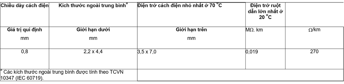
The insulation thickness shall conform to the values specified in Table 1, column 1.
The insulation resistance shall not be less than the value given in Table 1, column 4.
2.3.3 Core layout
Conductors shall be parallel and insulated.
The insulation shall be recessed on both sides between the conductors so that the cores can be easily separated.
2.3.4 External dimensions
The out-of-average dimensions shall be within the limits given in Table 1, column 2 and column 3.
2.4 Testing
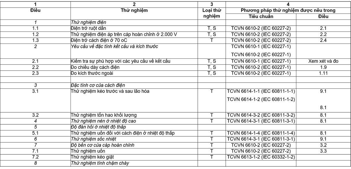
Compliance with the requirements of 2.3 is checked by inspection and by the tests given in Table 2.
2.5 User Manual
The maximum conductor temperature in normal use is 70 °C.
NOTE Other guidelines are under consideration.
3 Leave blank.
4 Soft wire for connecting indoor decorative lights
4.1 Code symbols
6610 TCVN 43 or 60227 IEC 43.
4.2 Rated voltage
300/300 V.
4.3 Texture
4.3.1 Conductor
Number of conductors: 1.
Conductors shall comply with the requirements given in IEC 60228) for class 6 conductors.
4.3.2 Insulation
Insulation shall be PVC/D grade PVC compound, shall consist of two layers and be sheathed by simultaneous extrusion around the conductor.
The outer layer of the insulation shall be of a color contrasting with the color of the inner layer but shall adhere to the inner layer.
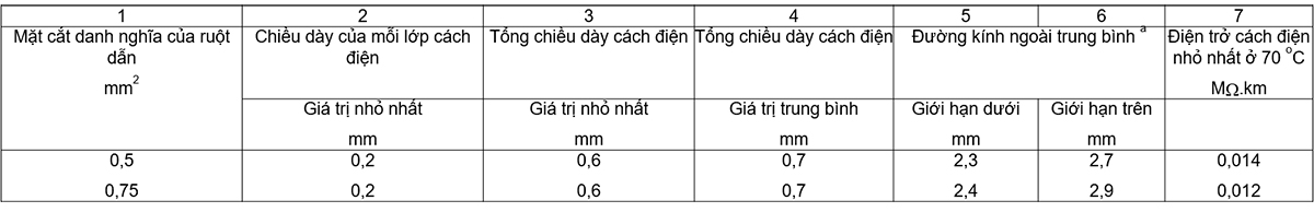
The sum of the thicknesses of the inner and outer layers of the insulation shall conform to the sum of the thicknesses specified in Tables 3, 3 and 4, but no point on each layer shall be less than the specified value. in column 2.
The insulation resistance at 70 °C shall not be less than the values given in Table 3, column 7.
4.3.3 Core recognition
Outer layer preferred color: green.
4.3.4 Outer Diameter
The mean outside diameters are within the limits given in Tables 3, 5 and 6.
4.4 Testing
4.4.1 General requirements
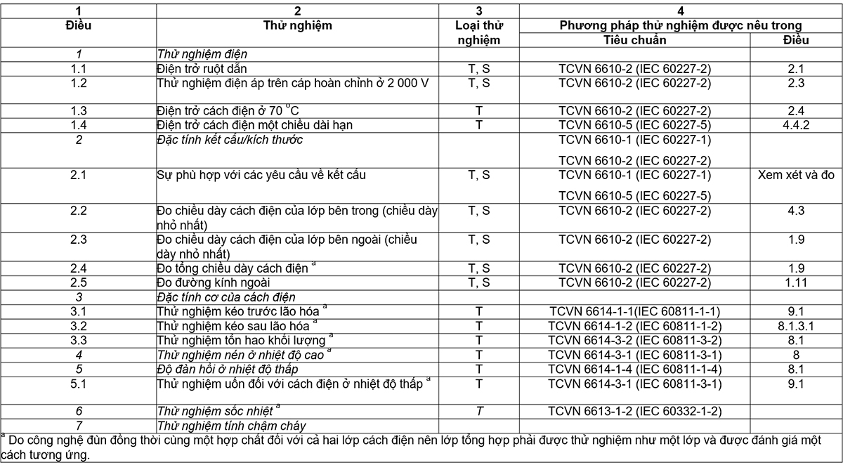
Compliance with the requirements of 4.3 is checked by inspection and by the tests given in Table 4, in addition by the long-term insulation resistance test with d.c. as given in 4.4.2.
4.4.2 Long-term insulation resistance with d.c
a) Test sample
The test is carried out on a sample of cable 5 m in length, completely unsheathed. Do not separate the cores of unshielded flat wire.
For cables up to five cores, each core shall be tested. For cables with more than five cores, test one core of each color of the cable and, in the case of colors less than 5, cores of the same color shall be tested as necessary to bring the number of cores tested to a minimum. 5.
Care should be taken to avoid damaging the core(s) during sheathing.
b) Process
Immerse the sample in a solution of sodium chloride with water, at a concentration of 10 g/l and at a temperature of (60 ± 5) °C, each end of the sample protruding about 250 mm above the solution. Connect the negative terminal of the 220 V d.c. power supply to the sample conductor(s) and the anode to a copper electrode immersed in solution for 240 h.
c) Request
There shall be no breakdown of the insulation during the test and, after the test, the exterior of the insulation shall show no sign of damage.
Discoloration of the insulation is ignored.
4.4.3 (Leave blank)
4.5 User Manual
The maximum conductor temperature in normal use is 70 °C.
5 Light PVC sheathed cord
5.1 Code symbols
6610 TCVN 52 or 60227 IEC 52.
5.2 Rated voltage
300/300 V.
5.3 Texture
5.3.1 Conductor
Number of conductors: 2 and 3.
Conductors shall comply with the requirements given in IEC 60228) for class 5 conductors.
5.3.2 Insulation
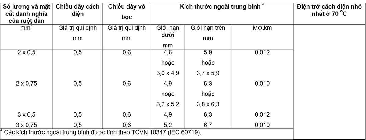
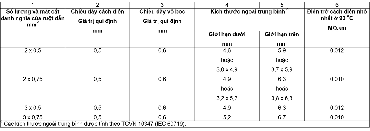
Insulation shall be of PVC/D grade PVC compound wrapped around each conductor. The insulation thickness shall conform to the values specified in Table 5, column 2.
The insulation resistance shall not be less than the values given in Table 5, column 6.
5.3.3 Core layout
Round flexible wire: the cores must be twisted together.
Flat flexible wire: cores must be placed parallel to each other.
5.3.4 Sheath
The sheath shall be of PVC/ST5 grade PVC compound wrapped around the cores. The sheath thickness shall conform to the value specified in Table 5, column 3.
The sheath may be inserted into the space between the cores, forming a filler but must not adhere to the core.
The core assembly can be wrapped with a separator that does not stick to the cores. The round flexible wire assembly shall have a relatively circular cross-section.
5.3.5 External dimensions
The mean outside diameters of round flexible cords and the mean outside dimensions of flat flexible cords shall be within the limits given in Table 5, column 4 and column 5.
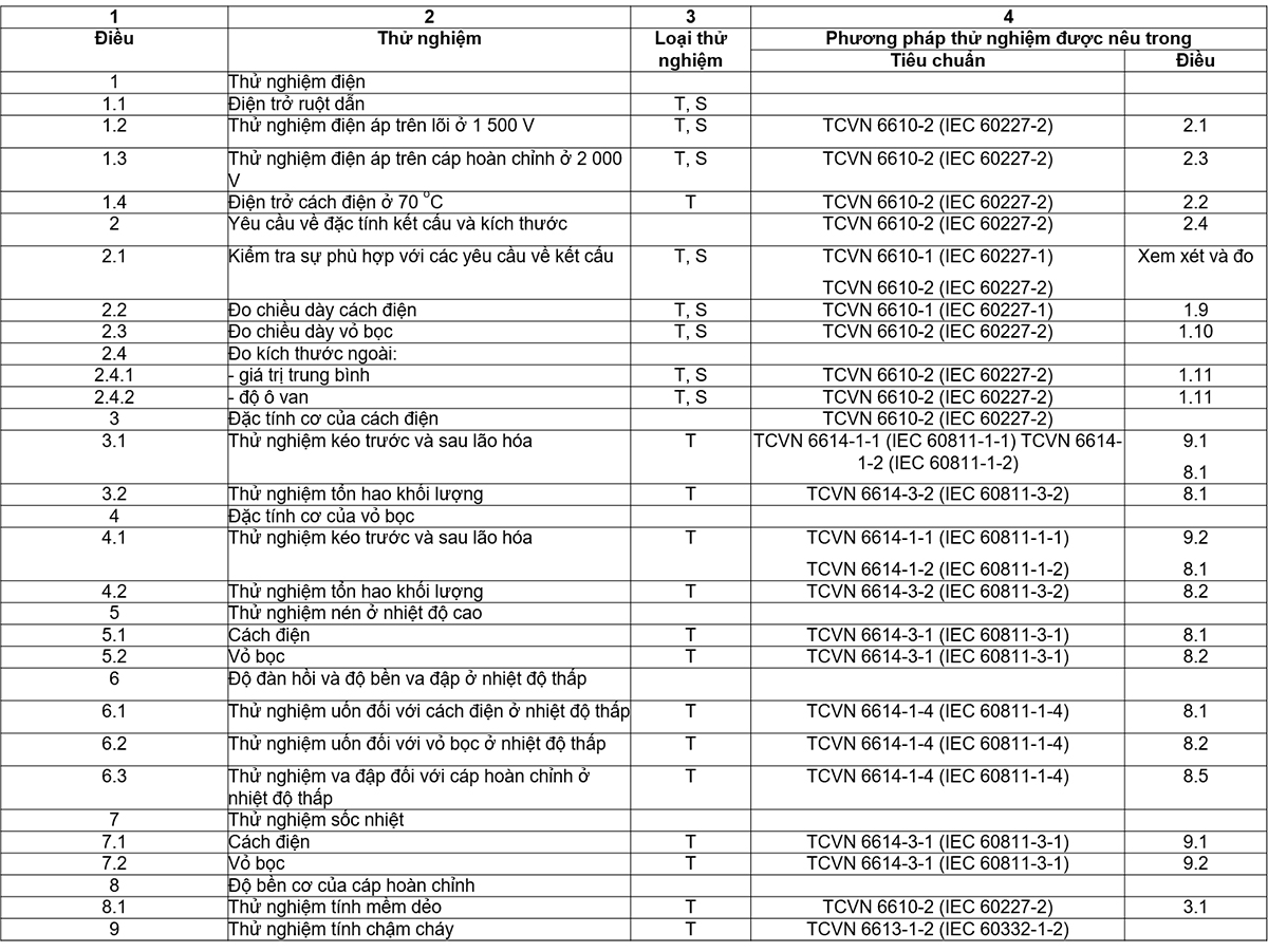
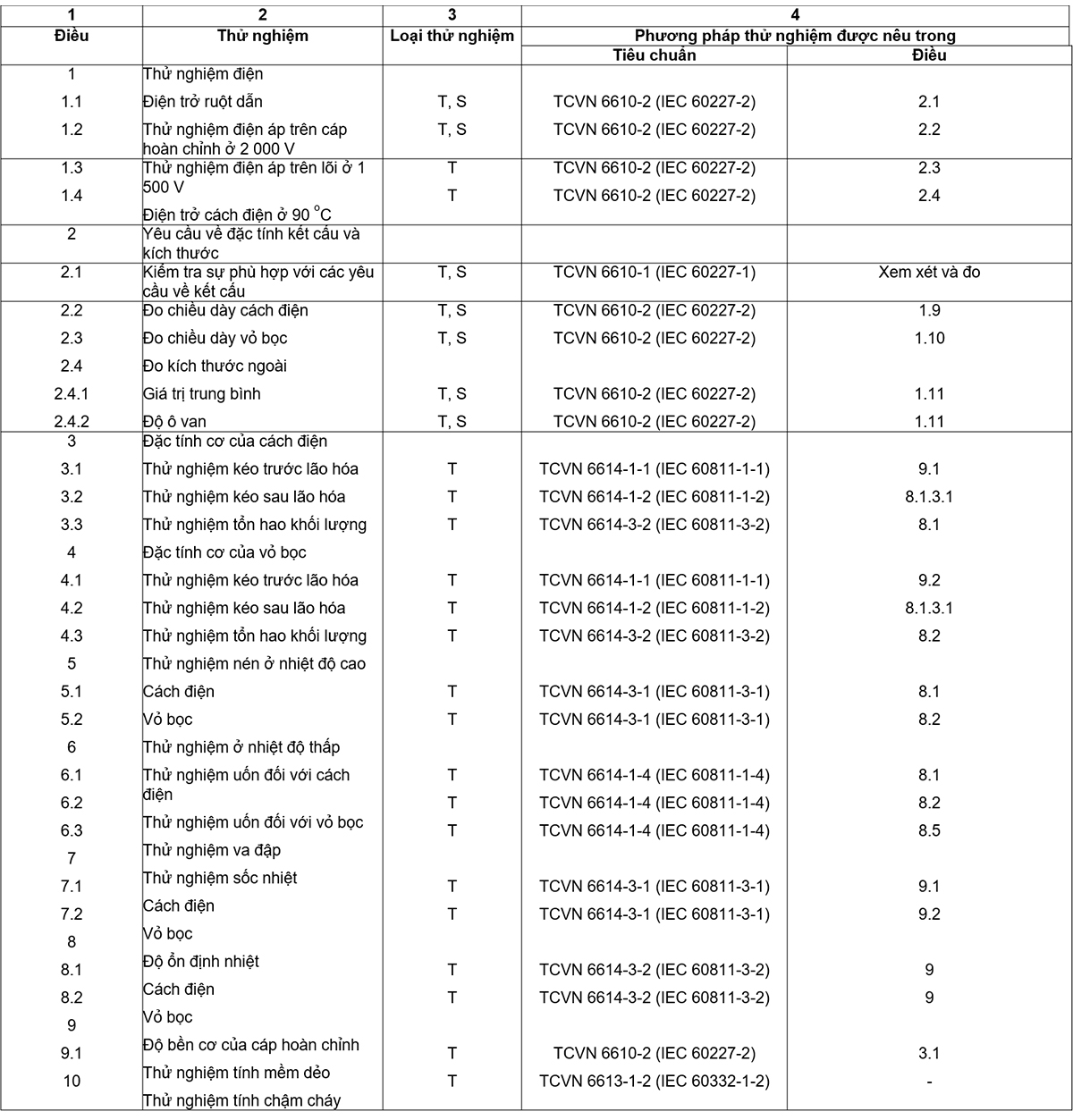
5.4 Testing
Compliance with the requirements of 5.3 is checked by inspection and by the tests given in Table 6.
5.5 User Manual
The maximum conductor temperature in normal use is 70 °C.
NOTE Other guidelines are under consideration.
6 Common PVC sheathed flexible cord
6.1 Code symbol
6610 TCVN 53 or 60227 IEC 53.
6.2 Rated voltage
300/500 V.
6.3 Textures
6.3.1 Conductor
Number of conductors: 2, 3, 4 or 5.
Conductors shall comply with the requirements given in IEC 60228) for class 5 conductors.
6.3.2 Insulation
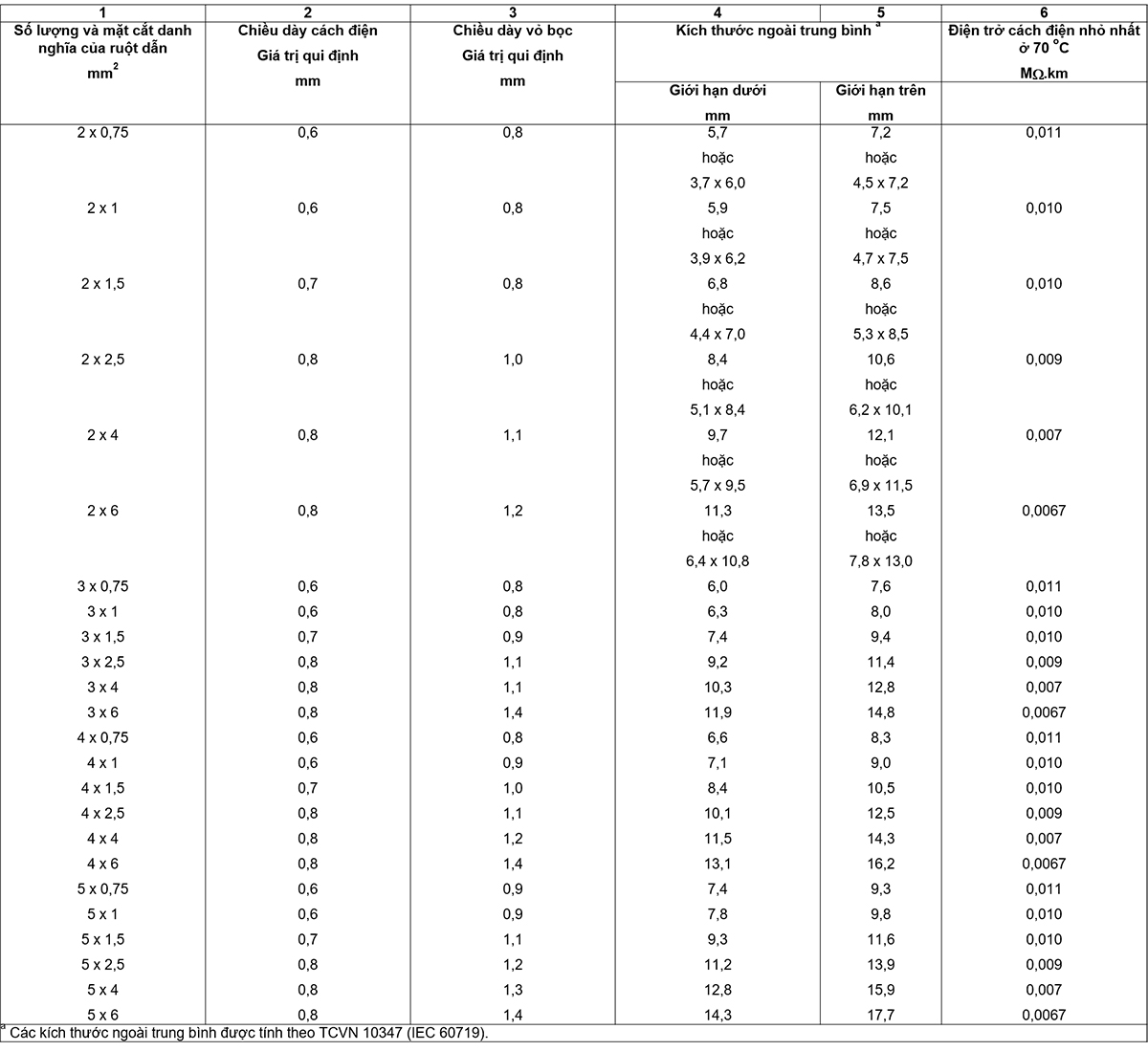
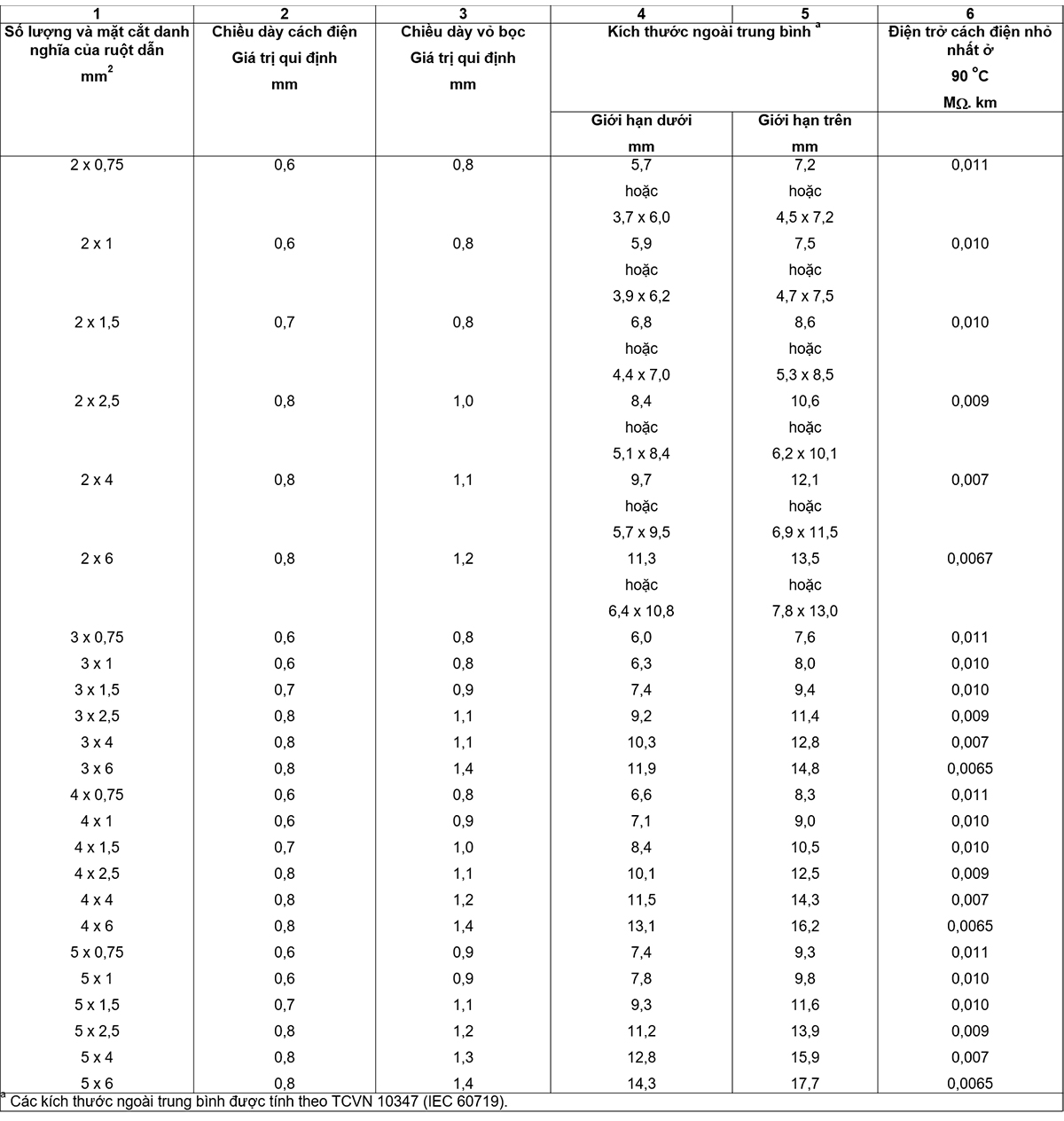
Insulation shall be of PVC/D grade PVC compound wrapped around each conductor. The insulation thickness shall conform to the value specified in Table 7, column 2.
The insulation resistance shall not be less than the values given in Table 7, column 6.
6.3.3 Core and filler arrangement, if any
Round soft wire: core and filler must be twisted together. Flat flexible wire: cores must lie parallel to each other.
For round flexible cords with two cores, the space between the cores shall be filled with a separate filler or by a sheath inserted into the junction.
Any fillers should not stick to the core.
6.3.4 Sheath
The sheath shall be of PCV/ST5 grade PVC compound wrapped around the cores. The sheath thickness shall conform to the values specified in Table 7, column 3.
The sheath may insert into the space between the cores, forming a filler, but must not stick to the core.
The core assembly can be wrapped with a separator that does not stick to the cores. The round flexible wire assembly shall have a relatively circular cross-section.
6.3.5 External dimensions
The mean outside diameter of round wire and the mean outside dimension of flat wire shall be within the limits given in Table 7, column 4 and column 5.
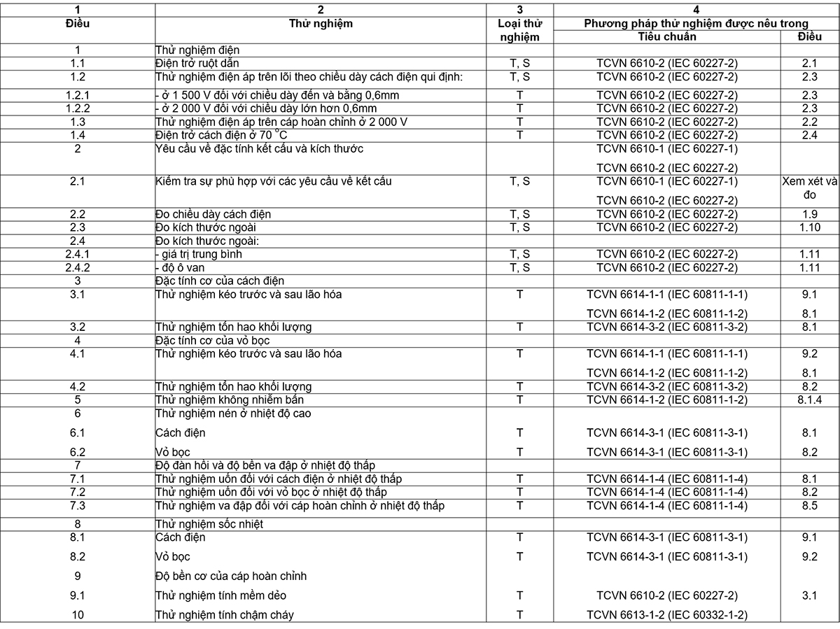
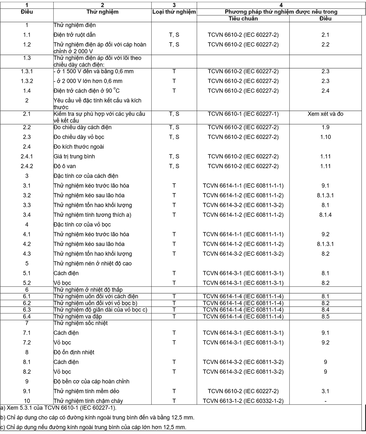
6.4 Testing
Compliance with the requirements of 6.3 is checked by inspection and by the tests given in Table 8.
6.5 User Manual
The maximum conductor temperature in normal use is 70 °C.
NOTE Other guidelines are under consideration.
7 Heat resistant lightweight PVC sheathed flexible wire for conductors with a maximum temperature of 90°C
7.1 Code symbols
6610 TCVN 56 or 60227 IEC 56.
7.2 Rated voltage
300/300 V.
7.3 Textures
7.3.1 Conductor
Number of conductors: 2 and 3.
Conductors shall comply with the requirements given in IEC 60228) for class 5 conductors.
7.3.2 Insulation
Insulation shall be of PVC/E class PVC compound wrapped around each conductor. The insulation thickness shall conform to the value specified in Table 9, column 2.
The insulation resistance shall not be less than the values given in Table 9, column 6.
7.3.3 Core layout
Round flexible wire: The cores must be twisted together.
Flat flexible wire: Cores must be placed parallel to each other.
7.3.4 Sheath
The sheath shall be of PVC/ST10 grade PVC compound wrapped around the core. The sheath thickness shall conform to the values specified in Table 9, column 3.
The sheath may insert into the space between the cores, forming a filler, but must not stick to the core. Core assemblies can be wrapped with separators without sticking to the cores.
The round flexible wire assembly shall have a relatively circular cross-section.
7.3.5 External dimensions
The mean outside diameters of round flexible cords and the mean outside dimensions of flat flexible cords shall be within the limits given in Table 9, column 4 and column 5.
7.4 Testing
Compliance with the requirements of 7.3 shall be checked by inspection and by the tests given in Table 10.
7.5 User Manual
The maximum conductor temperature in normal use is 90 °C.
NOTE Other guidelines are under consideration.
8 Heat resistant ordinary PVC sheathed flexible wire for conductors with a maximum temperature of 90 °C
8.1 Code symbols
6610 TCVN 57 or 60227 IEC 57.
8.2 Rated voltage
300/500 VUC
8.3 Textures
8.3.1 Conductors
Number of conductors: 2, 3, 4 or 5.
Conductors shall comply with the requirements given in IEC 60228) for class 5 conductors.
8.3.2 Insulation
Insulation shall be of PVC/E class PVC compound wrapped around each conductor. The insulation thickness shall conform to the values specified in Table 11, column 2.
The insulation resistance shall not be less than the values given in Table 11, column 6.
8.3.3 Core and filler arrangement, if any
Round flexible wire: core and filler, if any, must be twisted together. Flat flexible wire: The cores must lie parallel to each other.
For round flexible cords with two cores, the space between the cores shall be filled with a separate filler or by a sheath inserted into the junction.
Any fillers should not stick to the core.
8.3.4 Sheath
The sheath shall be of PVC/ST10 grade PVC compound wrapped around the core. The sheath thickness shall conform to the values specified in Table 11, column 3.
The sheath may insert into the space between the cores, forming a filler, but must not stick to the core. The core assembly can be wrapped with a separator that does not stick to the cores.
The round flexible wire assembly shall have a relatively circular cross-section.
8.3.5 External dimensions
The mean outside diameters of round flexible cords and the mean outside dimensions of flat flexible cords shall be within the limits given in Table 11, column 4 and column 5.
8.4 Test
Compliance with the requirements of 8.3 is checked by inspection and by the tests given in Table 12.
8.5 User Manual
The maximum conductor temperature in normal use is 90 °C.
NOTE Other guidelines are under consideration.
REFERENCES BIRD
[1] TCVN 6610-2:2007 (IEC 60227-2:2003), Polyvinyl chloride insulated cables with rated voltages up to and including 450/750 V – Part 2: Test methods [2] TCVN 6610-4 :2000 (IEC 60227-4:1992, amendment 1:1997), Polyvinyl chloride insulated cables of rated voltages up to and including 450/750 V – Part 4: Sheathed cables for fixed installations [3 ] TCVN 10347:2014 (IEC 60719:1992), Calculation of upper and lower limits of mean outer dimensions of cables with round copper conductors and rated voltages up to and including 450/750 V [4 ] BS 6004:2012, Electric cables – PVC insulated and PVC sheathed cables for voltages up to and including 300/500 V, for electric power and lighting and equal to 300/500 V for electricity and lighting)
TABLE OF CONTENTS
1 General Provisions
1.1 Scope of application
1.2 References
2 flat tinsel wire
2.1 Code symbols
2.2 Nominal voltage
2.3 Texture
2.4 Testing
2.5 User Manual
3 Leave it blank
4 Soft wire for connecting indoor decorative lights
5 Lightweight PVC sheathed flexible cord
6 Common PVC sheathed flexible cord
7 Heat resistant lightweight PVC sheathed flexible cord for use at a maximum conductor temperature of 90oC
8 Heat resistant ordinary PVC sheathed flexible wire for conductors with a maximum temperature of 90oC.