NATIONAL STANDARDS
LAMP INSULATED ELECTRICAL CABLES AND CABLE ACCESSORIES FOR Rated VOLTAGE FROM 1 kV (Um=1.2kV) TO 30 KV (Um=36kV) – PART 2: CABLES FOR Rated Voltage FROM 6 kV (Um= 7.2 kV) TO 30 kV (Um=30kV)
Power with cables extruded insulation and their accessories for rated voltages from 1 kV (Um = 1.2 kV) up to 30 kV (Um = 36 kV) – Part 2: Cables for rated voltages from 6kV (Um = 7.2 kV) and 30 kV (UM = 36 kV).
2013-Cap-dien-cach-dien-dang-dun-Phan-2-dien-ap-6kV-den-30kV” />
LAMP INSULATED ELECTRICAL CABLES AND CABLE ACCESSORIES FOR Rated VOLTAGE FROM 1 kV (Um=1.2kV) TO 30 KV (Um=36kV) – PART 2: CABLES FOR Rated Voltage FROM 6 kV (Um= 7.2 kV) TO 30 kV (Um=30kV)
Power with cables extruded insulation and their accessories for rated voltages from 1 kV (Um = 1.2 kV) up to 30 kV (Um = 36 kV) – Part 2: Cables for rated voltages from 6kV (Um = 7.2 kV) and 30 kV (UM = 36 kV)
Preface
TCVN 5935-1:2013 and TCVN 5935-2:2013 replace TCVN 5935:1995;
TCVN 5935-2:2013 is completely equivalent to IEC 60502-2:2005;
TCVN 5935-2:2013 compiled by the National Technical Committee for National Standards TCVN/TC/E4 Electrical wires and cables, proposed by the General Department of Standards, Metrology and Quality, and published by the Ministry of Science and Technology.
IEC 60502 series, Electrical cables with extruded insulation and cable accessories for rated voltages from 1 kV (Um = 1.2 kV to 3 kV (Um = 3.6 kV), including the next part:
TCVN 5935-1:2013 (IEC 60502-1:2009), Part 1: Cables for rated voltages of 1 kV (Um = 1,2 kV) and 3 kV (Um = 3.6 kV)
TCVN 5935-2:2013 (IEC 60502-2:2005), Part 2: Cables for rated voltages from 6 kV (Um = 7.2 kV) to 30 kV (Um = 36 kV)
TCVN 5935-4:2013 (IEC 60502-4:2005), Part 4: Test requirements for cable accessories with rated voltages from 6 kV (Um = 7.2 kV) to 30 kV (Um = 36 kV)
LAMP INSULATED ELECTRICAL CABLES AND CABLE ACCESSORIES FOR Rated VOLTAGE FROM 1 kV (Um=1.2kV) TO 30 KV (Um=36kV) – PART 2: CABLES FOR Rated Voltage FROM 6 kV (Um= 7.2 kV) TO 30 kV (Um=30kV)
Power with cables extruded insulation and their accessories for rated voltages from 1 kV (Um = 1.2 kV) up to 30 kV (Um = 36 kV) – Part 2: Cables for rated voltages from 6kV (Um = 7.2 kV) and 30 kV (UM = 36 kV)
This standard specifies the requirements for construction, dimensions and testing of electrical cables with extruded solid insulation of rated voltage from 6 kV to 30 kV for fixed installations such as distribution grids or power systems. industrial installations.
When determining applications, consideration should be given to the risk of radial water ingress of the cable. The design of the cable has a barrier that can prevent longitudinal water ingress and the relevant test is given in this standard.
Cables for special installations and special operating conditions not covered by this standard, e.g. cables for overhead lines, the mining industry, nuclear power plants (in and around radioactive areas), cables for underground use under the sea or for shipboard applications.
The following referenced documents are necessary for the application of the standard. For dated references, the cited version applies. For undated references, the most recent version, including any amendments, applies.
IEC 60060-1, High voltage test techniques – Part 1: General definitions and test requirements
IEC 60228, Conductors of insulated cables
IEC 60332-1-2, Tests of electrical and optical cables under fire conditions – Part 1-2: Test of vertical fire propagation for an insulated wire or a cable – Process for a premixed gas fire source with a capacity of 1 kW
IEC 60811-1-1, General test methods for insulating and sheathing materials of electrical and optical cables – Part 1-1: Method of general application Measurement of thickness and outer dimensions – Mechanical characterization test
IEC 60811-1-2, General test methods for insulating and sheathing materials of electrical and optical cables – Part 1-2: Method of general application Heat aging method
IEC 60811-1-3, General test methods for insulating and sheathing materials of electrical and optical cables – Part 1-3: Method of general application – Density method – Water absorption test – Shrinkage test
IEC 60811-1-4, General test methods for insulating and sheathing materials of electrical and optical cables – Part 1-4: Method of general application Test at low temperature
IEC 60811-2-1, General test methods for insulating and sheathing materials of electric and optical cables – Part 2-1: Specified methods for compliance elastomers – Ozone resistance test, furnace stretching test and mineral oil immersion test
IEC 60811-3-1, General test methods for insulating and sheathing materials of electrical and optical cables – Part 3-1: Specified methods for compliance PVC material – High temperature compression test – Crack resistance test
IEC 60811-3-2, General test methods for insulating and sheathing materials of electrical and optical cables – Part 3-2: Specified methods for compliance PVC material – Mass loss test – Thermal stability test
TCVN 7995 (IEC 60038), Standard voltage
IEC 60183, Guide to the selection of high-voltage cables
IEC 60229, Tests on cable oversheaths which have a special protective function and are applied by extrusion
IEC 60230, Impulse tests on cables and their accessories
IEC 60811-4-1, Insulating and sheathing materials of electric and optical cables – Common test methods – Part 4-1: Methods specific ti polyethylene and polypropylene compounds – Resistence to environmental stress cracking – Measurement of the melt flow index – Carbon balck and /or mineral filler content measurement in polyethylene by direct combustion – Measurement of carbon black content by thermogravimetric analysis (TGA) – Assessment of carbon black dispresion in polyethylene using a microscope (General test methods – Part 4-1:Specified method for polyethylene and polypropylene compounds – Environmental stress cracking resistance – Flow index measurement – Measurement of coal black powder and/or mineral filler content in polyethylene by direct combustion – Measurement of content Charcoal black powder by thermogravimetric analysis (TGA) – Evaluation of the dispersion of carbon black content in polyethylene using microscopy)
IEC 60885-3, Electrical test methods for electric cables – Part 3: Test methods for partial discharge measurements on lengths of extruded power cables partial discharge over the length of the extruded power cable)
IEC 60986, Short-circuit temperature limits of electric cables with rated voltages from 6 kV (Um = 7.2 kV) up to 30 kV (Um = 36 kV) from 6 kV (Um = 7.2 kV) to 30 kV (Um = 36 kV)
ISO 48, Rubber, vulcanized or thermoplastic – Determination of hardness (hardness between 10 IRHD and 100 IRHD)
In this standard, the following terms and definitions apply.
3.1 Define dimension values (thickness, cross-section, etc.)
3.1.1
nominal value
A specified value for a quantity and commonly used in tables.
NOTE In this standard it is common for the nominal value to be the basis of the values to be checked by measurement taking into account the specified tolerances.
3.1.2
Approximate value
Values are neither guaranteed nor tested; This value is used, for example, to calculate other dimension values.
3.1.3
Median value
When several test results are obtained and arranged in ascending (or descending) order, the middle value is the middle value if the number of available values is odd and is the average of the two values. between if the number of values is even.
3.1.4
fictitious value
The value is calculated according to the “hypothetical method” described in Annex A.
3.2 Definitions related to tests
3.2.1
Routine tests
Test carried out by the manufacturer on each manufactured cable segment to verify the compliance with the specified requirements of each section of cable.
3.2.2
Sample tests
Test carried out by the manufacturer on samples of completed cables or sections taken from complete cables at specified frequencies to verify that the finished product meets specified requirements.
3.2.3
Type tests
Test made prior to supplying, on a general commercial basis, a type of cable specified in this standard demonstrating satisfactory performance characteristics to meet the intended application.
NOTE These tests are of the nature that, once performed, they do not need to be repeated unless changes in the material or design of the cable manufacturing process may alter the characteristics. about features.
3.2.4
Electrical tests after installation
The test is performed to demonstrate the integrity of the cable and its accessories after installation.
4 Voltage symbols and materials
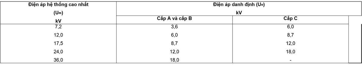
The rated voltages Uo/U(Um) of the cables considered in this standard are as follows:
Uo/U(Um) = 3.6/6 (7.2) – 6/10 (12) – 8.7/15 (17.5) – 12/20 (24) – 18/10 (36) kV .
NOTE 1 The above voltages are the correct symbols although in some countries other symbols are used, e.g. 3.5/6 – 5.8/10 – 11.5/20 – 17.3 /30 kV.
In the way the voltage symbol of the cable is Uo/U(Um)
Uo is the rated power-frequency voltage between the conductor and earth or the metallic screen for which the cable is designed.
U is the rated power-frequency voltage between conductors for which the cable is designed;
Um is the highest value of the “highest system voltage” that the equipment is allowed to use (see IEC 60038).
The rated voltage of the cable for a given application shall be suitable for the operating conditions in the system in which the cable is used. For the convenience of cable selection, the system is divided into the following three levels:
– Class A: this class includes systems in which the phase conductor, upon earthing or earthing, is disconnected from the system within 1 min;
– Class B: This class includes systems that in fault conditions still work for a short time with one phase to earth. According to IEC 60183, this time should not exceed 1 h. For cables covered by this standard, longer periods of time, but not exceeding 8 h in any case, may be accepted. Total time of occurrence of earth fault in any year should not exceed 125 h;
– Class C: this class includes all systems that are not in class A or B.
NOTE 2 It is known that in a system where the earth fault is not isolated automatically and rapidly, abnormal stresses on the cable insulation during the earth fault will reduce the life of the cable. to a certain extent. If the system is expected to operate fairly frequently with prolonged earth faults, the system should be classified in class C.
Recommended Uo values for cables used in three-phase systems are listed in Table 1.
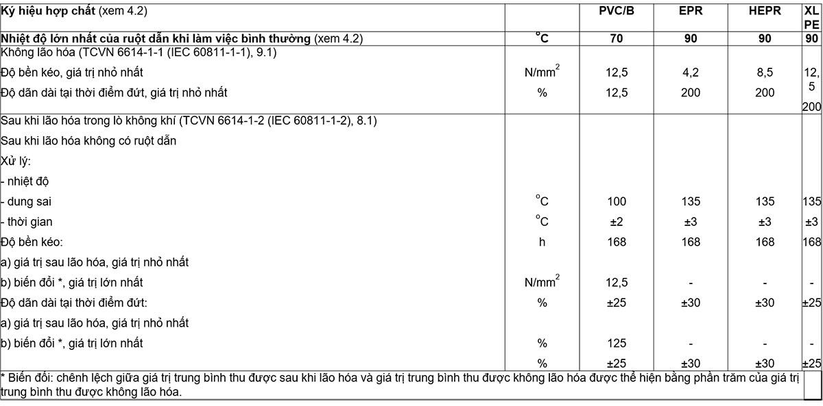
The highest conductor temperatures for the different classes of insulating compounds covered by this standard are given in Table 3.
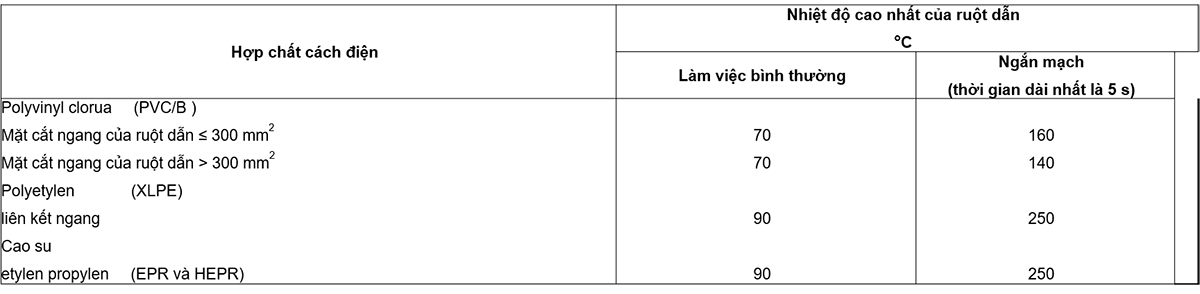
The temperatures in Table 3 are based on the inherent properties of the insulating material. It is important to take other factors into account when using these values to calculate the current rating.
For example, under normal operating conditions, if a cable is buried directly in the ground for continuous load operation (100 % load factor) at the highest conductor temperature shown in the table, then, over time , the thermal resistance of the soil around the cable may increase from its original value due to the drying process of the soil. As a result, the conductor temperature can greatly exceed the highest value. If it is foreseen that such working conditions will be, then adequate provision should be made.
Refer to Appendix B for guidance on the continuous current rating.
Refer to IEC 60986 for guidance on short circuit temperatures.
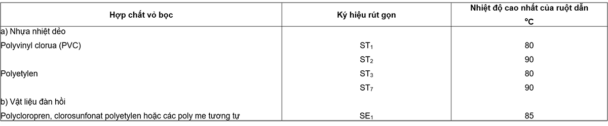
The highest conductor temperatures for the different types of sheathing compounds covered by this standard are given in Table 4.
5 Conductors
The conductors shall be class 1 or class 2 of uncoated or metallized annealed copper of aluminum or aluminum alloy in accordance with IEC 60228. For class 2 conductors, measures may be taken to achieve longitudinal waterproofing.
6.1 Materials
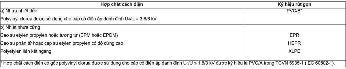
The insulation shall be an extruded dielectric of one of the classes listed in Table 2.
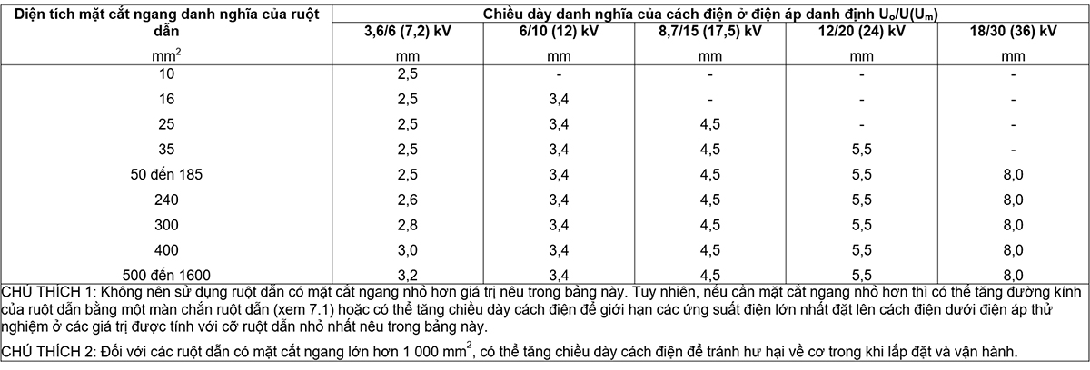
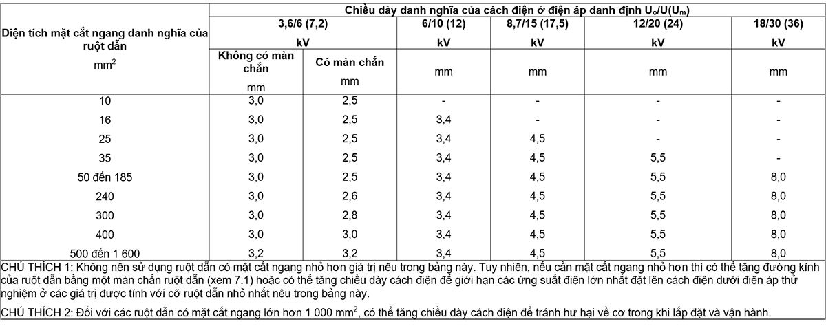
6.2 Insulation thickness
The nominal insulation thicknesses are specified in the tables from Tables 5 to 7.
The thickness of any separator or semiconductor screen on the conductor or outside the insulation is not included in the insulation thickness.
7 Curtains
All cables must have a metallic layer around the cores, either on individual cores or on the core assembly as a whole.
The shielding of individual cores in single-core or three-core cables, when required, shall include a conductor screen and a screen of insulation. These screens shall be used on all cables, except:
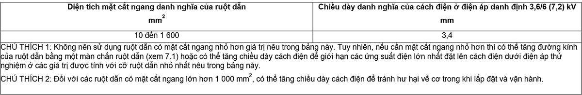
a) at a rated voltage of 3,6/6 (7.2) kV, cables insulated with EPR and HEPR may be screenless provided that an insulation thickness greater than that given in Table is used. 7;
b) at a rated voltage of 3,6/6 (7.2) kV, PVC insulated cables shall not be screened.
7.1 Conductor screen
The conductor screen shall be of non-metallic material and shall be of extruded semiconductor compound, which may be placed on top of a semiconductor ribbon. The extruded semiconductor compound shall be firmly bonded to the insulation.
7.2 Insulation screen
The insulating screen shall consist of a non-metallic semiconductor layer combined with a metallic layer.
The non-metallic layer shall be extruded directly onto the insulation of each core and made of an adherent or peelable semiconductor compound.
The semiconductor ribbon or compound layer can then be placed on individual cores or core assemblies.
The metal layer shall be applied to each core individually or on the core assembly and shall comply with the requirements of Clause 10.
8 Three-core cable assembly, inner sheath and filler
The three-core cable assembly depends on the rated voltage and whether a metal screen is applied to each core.
Clauses 8.1 to 8.3 do not apply to sheathed single-core cable assemblies.
8.1 Inner coating and filler
8.1.1 Texture
The inner wrap can be extruded or wound.
For cables with round cores, a wound inner covering is allowed only if the space between the cores is substantially filled.
Allows the use of a suitable bundle layer prior to extrusion of the inner wrap.
8.1.2 Materials
The material used for the inner covering and filler shall be suitable for the operating temperature of the cable and compatible with the insulating material.
8.1.3 Thickness of extruded inner coating
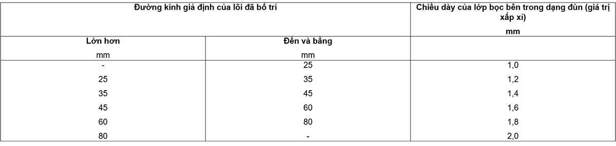
The approximate thickness of the extruded inner coating shall be obtained from Table 8.
8.1.4 Thickness of wound inner covering
The approximate thickness of the wound inner covering is 0.4 mm for fictitious core diameters arranged up to and including 40 mm and 0.6 mm for larger diameters.
8.2 Cables with common metallic layer (see Clause 9)
The cable shall have an inner sheath surrounding the arranged core. The inner sheath and filler shall be in accordance with 8.1 and shall not be hygroscopic unless the cable is declared to be longitudinally watertight.
For cables with a semiconductor screen surrounding each individual core and a common metal layer, the inner covering shall begin with a semiconductor; The filler can be semiconductor.
8.3 Cables with a metallic layer surrounding each individual core (see Clause 10)
The metal layers of each individual core must be in contact with each other.
Layers with complementary common metal (see Clause 9) of material identical to that of the individual metallic layers below shall have an internal covering surrounding the arranged cores. The inner sheath and filler shall be in accordance with 8.1 and shall not be hygroscopic unless the cable is declared to be longitudinally watertight. The inner coating and filler may be semiconductor.
When the individual underlying metal layers and the common metal layer are of different materials, they shall be separated by an extruded sheath of one of the materials specified in 14.2. For lead-sheathed cables, separation from the individual metal layers below may be made by means of an inner sheath according to 8.1.
For cables without a metallic layer in common (see Clause 9) the inner sheath may be omitted provided that the external shape of the cable is essentially circular.
9 Metallic layers of single-core and three-core cables
The following types of metallic grades are covered in this standard:
a) metal screens (see Clause 10);
b) concentric conductors (see Clause 11);
c) metal enclosures (see Clause 12);
d) metal armor (see Clause 13).
The metallic layer(s) shall consist of one or more of the types listed above and shall be non-magnetic when applied to a single-core cable or to individual cores of a three-core cable.
Measures may be taken to achieve longitudinal watertightness in the region of metallic layers.
10.1 Textures
The metal screen shall be one or more ribbons, or a woven mesh or a layer of concentric wire, or a combination of wires and ribbon(s).
The metal screen may also be an enclosure or armor in the case of a general screen in accordance with 10.2.
When selecting screen materials, special consideration must be given to the possibility of corrosion, not only for mechanical safety but also for electrical safety.
The clearance in the screen shall be in accordance with national regulations and/or national standards.
10.2 Requirements
The dimensional, physical and electrical requirements of metal screens shall be defined in national regulations and/or national standards.
10.3 Non-coupled metal screens with semiconductor layers
In the case of metal screens used at rated voltages of 3.6/6 (7.2) kV, with PVC, EPR and HEPR insulation, these screens are not required to incorporate a semiconductor layer. .
11.1 Textures
Clearances in concentric conductors shall comply with national regulations and/or national standards.
When selecting concentric conductor materials, special consideration must be given to the possibility of corrosion, not only for mechanical safety but also for electrical safety.
11.2 Requirements
Dimensional, physical and electrical requirements of concentric conductors shall be defined in national regulations and/or national standards.
11.3 Concentric conductor placement
Where a concentric conductor is required, this concentric conductor shall be placed over the inner sheath in the case of three-core cables; in the case of single-core cables, the concentric conductors shall be applied directly on the insulation or on a screen of semiconductor insulation or on a suitable inner covering.
12.1 Lead sheath
The sheath shall be of lead or lead alloy and shall be laid as a reasonably tight-fitting seamless tube.
The nominal thickness shall be calculated according to the following formula:
a) for all single-core cables or single-core cable assemblies
tpb = 0.03 Dg + 0.8
b) for all cables with fan conductors up to and including 8.7/15 kV:
tpb = 0.03 Dg + 0.6
c) for all other cables:
tpb = 0.03 Dg + 0.7
Inside:
tpb is the nominal thickness of the lead sheath, in millimetres;
Dg is the assumed diameter under the lead sheath, in millimeters (rounded to decimals
first division according to Appendix C)
In all cases, the minimum nominal thickness shall be 1,2 mm. Calculated values must
rounded to the first decimal place (see Appendix C).
12.2 Other metal enclosures
Is considering
13.1 Types of Metal Armor
The types of armor covered by this standard are as follows:
a) flat wire armor;
b) armor of round wire;
c) double tape armor;
13.2 Materials
Round wire or flat wire shall be galvanized steel, copper or tin coated copper, aluminum or aluminum alloy.
The ribbon must be steel, galvanized steel, aluminum or aluminum alloy. Steel strip shall be hot-rolled or cold-rolled of commercial quality.
In cases where a suitable steel armor wire layer with minimum conductivity is required, it is permissible to add sufficient quantities of tinned copper or copper wires in the armor layer to ensure compliance.
When choosing armor materials, special consideration must be given to the possibility of corrosion, not only for mechanical safety but also for electrical safety, especially when armor is used as a screen.
Armor of single-core cables for use in a.c. systems shall be of non-magnetic material, unless specially constructed armor is selected.
13.3 Placing armor
13.3.1 Single-core cable
In the case of single-core cables, an extruded or wound inner covering of the thickness specified in 8.1.3 or 8.1.4 shall be placed under the armor if no screen is provided.
13.3.2 Three-core cable
When armor is required in the case of three-core cables, the armor shall be placed over the inner sheath in accordance with 8.1.
13.3.3 Separation sheath
Where the underlying metal and armor are made of different materials, they shall be separated by extruded sheath of one of the materials specified in 14.2.
When armor is required for sheathed cables, the armor may be placed on top of the separation sheath or on top of the wound lining according to 13.3.4.
If separation sheath is used, it must be placed under the armor in place of the inner sheath or in addition to the inner sheath.
No separation enclosure is required when measures are taken to achieve longitudinal watertightness in the region of the metallic layers.
The nominal thickness of the separation sheath Ts, in millimeters, shall be calculated from the following formula:
Ts = 0.02 Du + 0.6
where Du is the assumed diameter under this sheath, in millimetres, calculated as described in Annex A.
The value calculated from this formula shall be rounded to the nearest 0.1 mm (see Annex C).
For cables without lead sheath, the nominal thickness shall not be less than 1,2 mm. For cables in which the separating sheath is placed directly over the lead sheath, the nominal thickness shall not be less than 1,0 mm.
13.3.4 Wrap-up underarmor for lead-sheathed cables
Wrap liner applied to a suitable lead sheath of impregnated paper tapes and in the form of a compound or combination of two layers of impregnated paper tape and in the compound form followed by one or more layers of suitable material fibrous matter.
Impregnation of the lining material can be done with bituminous compounds or other preservative compounds. In the case of wire armor, these compounds should not be placed directly under the armor.
Synthetic bandages may be used instead of impregnated paper tapes.
The total thickness of the wrap lining between the lead sheath and the armor after armor placement shall be approximately 1.5 mm.
13.4 Dimensions of armor wire and armor ribbon
The nominal size of the armor wire and the best armor band is one of the following:
Round rope:
Diameter 0.8 – 1.25 – 1.6 – 2.0 – 3.15 mm;
Flat wire:
Thickness 0.8 mm;
Steel ribbon:
Thickness: 0.2 – 0.5 – 0.8 mm;
Aluminum or aluminum alloy ribbon:
Thickness 0.5 – 0.8 mm;
13.5 Relationship between cable diameter and armor size
The nominal diameter of the armor round wire and the nominal thickness of the armor band shall not be less than the values given in Tables 9 and 10 respectively.
For flat wire armor and the assumed diameter under the armor is more than 15 mm, the nominal thickness of the flat wire shall be 0.8 mm. Cables of assumed diameter under armor up to and including 15 mm shall not be armored with flat wire.
13.6 Round or flat wire armor Wire
armor should be tight, i.e. with minimal clearance between adjacent wires. Galvanized steel cuffs with a nominal thickness of at least 0.3 mm may be used spirally wound over the armor with flat wire and over the armor with round wire, if necessary. The tolerances of the steel band shall be in accordance with 17.7.3.
13.7 Double Band Armor
When tape armor and an inner covering as specified in 8.1 are used, the inner covering shall be reinforced with a tape liner. The total thickness of the inner covering and the additional tape liner shall be as specified in 8.1 plus 0,5 mm if the thickness of the armor band is 0.2 mm and plus 0.8 mm if the thickness of the armor band is more than 0.2 mm.
The total thickness of the inner wrap and the additional tape-type lining shall not be less than these values by more than 0,2 mm with a tolerance of ±20%.
If separation sheath is required or if the inner covering is extruded and meets the requirements of 13.3.3, no additional ribbon-type lining is required.
Bandage armor shall be spirally wound in two layers so that the outer band is approximately centered over the gap in the inner band. The clearance between adjacent loops of each ribbon shall not exceed 50 % of the width of the tape.
14 Sheath
14.1 General
All cables must have an oversheath.
The sheath is normally black, but other colors may be used by agreement between manufacturer and purchaser, but this color shall be appropriate to the particular conditions in which the cable is to be used.
NOTE The UV stability test is under consideration.
14.2 Material
The sheath shall be a thermoplastic compound (PVC or polyethylene) or an elastomer compound (polychloroproprene, polyethylene chlorosulphonate or similar polymer).
The sheath material shall be suitable for the operating temperatures in accordance with Table 4.
Chemical additives to the sheath may be required for special purposes, for example termite protection, but should not contain such materials. harmful to people and/or the environment.
NOTE Examples of materials1 considered unsuitable include:
• Aldrin: 1,2,3,4,10,10-hexachloro-1,4,4a,5,8,8a-hexahydro-1 ,4,5,8-dimethanonaphthalene
• Dieldrin: 1,2,3,4,10,10-hexachloro-6,7-epoxy-1,4,4a,5,6,7,8,8a-octahydro-1 ,4,5,8-dimethanonaphthalene
• Lindane: Gamma Isomer of 1,2,3,4,5,6-hexachloro-cyclohexane.
14.3 Thickness
Unless otherwise specified, the nominal thickness ts in millimetres shall be calculated from the following formula:
ts = 0.035 D + 1,0
where, D is the assumed diameter immediately under the sheath, calculated in millimeters (see Annex A).
The value obtained from this formula shall be rounded to the nearest 0,1 mm (see Annex C).
For unarmoured cables and sheathed cables not applied directly to armor, metallic screens or concentric conductors, the nominal thickness shall be not less than 1.4 mm for single-core cables and 1 ,8 mm for three-core cable.
For cables with an oversheath applied directly to armor, metallic sheath or concentric conductors, the rated thickness shall not be less than 1,8 mm.
15 Test conditions
15.1 Ambient temperature
Unless otherwise specified in the detailed description for a particular test, the tests shall be carried out at an ambient temperature of (20 ± 15) oC.
15.2 Frequency and waveform of power-frequency test voltages The frequency of the
a.c. test voltages shall be in the range 49 Hz to 61 Hz. The waveform is basically a sine wave. The values quoted are effective values.
15.3 Impulse test voltage waveform
According to IEC 60230, the impulse wave shall have a real front time from 1 µs to 5 µs a nominal time to half-peak value between 40 µs and 60 µs. In other respects it shall be in accordance with IEC 60060-1.
16 Routine test
16.1 General
Routine tests are normally made on each length of cable (see 3.2.1). However, the number of cable segments to be tested may be reduced or an alternative test method adopted, according to agreed quality control procedures.
The routine tests required in this standard are:
a) Measurement of conductor resistance (see 16.2);
b) Partial discharge test (see 16.3) on cables with conductor screen cores and insulating screens according to 7.1 and 7.2;
c) Voltage test (see 16.4).
16.2 Conductor resistance Resistance
measurement shall be made on all conductors of each cable segment submitted for routine testing, including concentric conductors, if any.
The complete cable length, or a sample from this length, shall be placed in a test room maintained at a reasonably constant temperature, for at least 12 h prior to the test. In case of doubt as to whether the conductor temperature is the same as room temperature, the resistance shall be measured after the cable has been placed in the test room for 24 h. Alternatively, the resistance can be measured on a sample of conductor conditioned for at least 1 h in a temperature controlled liquid bath.
The measured resistance value shall be corrected to a temperature of 20°C and 1 km of length according to the formulas and coefficients given in IEC 60228.
The d.c. resistance of each conductor at 20 °C shall not exceed the appropriate maximum value specified in IEC 60228. For concentric conductors, the resistance shall comply with national regulations and/or standards.
16.3 Partial discharge test Partial
discharge test shall be carried out in accordance with IEC 60885-3 except that the sensitivity as specified in IEC 60885-3 shall be 10 pC or better.
For three-core cables, the test shall be made on all insulated cores, the voltage applied between each conductor and the screen.
The test voltage shall be raised slowly and held at 2 Uo for 10 s and then decreased slowly to 1,73 Uo.
There shall be no detectable discharge exceeding the declared sensitivity from the test object at 1.73 Uo.
NOTE Any partial discharge from the test object can be harmful.
16.4 Voltage test
16.4.1 General
The voltage test shall be carried out at ambient temperature using a.c. voltage at power frequency.
16.4.2 Test procedure for single-core cables
For single-core cables, the test voltage shall be applied for 5 min between the conductor and the metal screen.
16.4.3 Test procedure for three-core cables
For three-core cables with individually screened cores, the test voltage shall be applied for 5 min between each conductor and the metallic layer.
For three-core cables without separate screens, the test voltage shall be applied for 5 min in turn between each insulated conductor and all remaining conductors and the common metallic layers.
Three-core cables can be tested in one operation using a three-phase transformer.
1.6.4.4 Test voltage
The power frequency test voltage shall be 3.5 Uo. The value of single-phase test voltage for standard rated voltage is given in Table 11.

For three-core cables, if the voltage test is made with a three-phase transformer, the test voltage between phases shall be 1,73 times the value given in the table.
In all cases, the test voltage shall be gradually increased to the specified value.
16.4.5 Requirements
Insulation breakdown shall not occur.
17.1 General requirements
Sample tests required in this standard are as follows:
a) check the conductors (see 17.4);
b) check the dimensions (see clauses 17.5 to 17.8);
c) voltage test for cables with rated voltage greater than 3,6/6 (7.2) kV (see 17.9);
d) Heat-furnace stretching test for EPR, HEPR and XLPE insulation and elastomeric sheath (see 17.10).
17.2 Sample test frequency
17.2.1 Conductor check and dimensional check
Conductor inspection, insulation and sheath thickness measurements and outside diameter measurements shall be carried out on a length of cable from each manufacture series of the same type and nominal cross-section of the cable but shall be limited to not more than 10% of the cable segments in any contract.
17.2.2 Electrical and physical tests
Electrical and physical tests shall be performed on samples taken from fabricated cables according to an agreed quality control procedure. In the absence of this agreement, for contracts where the total length exceeds 2 km for three-core cables or 4 km for single-core cables, the test shall be carried out according to Table 12.
17.3 Repeat the test
If any sample fails any of the tests in Clause 17, two more samples shall be taken from the same lot and subjected to the same or more tests in which the original sample fails. If both additional samples pass the test, all cables in the lot from which the samples are taken shall be deemed to comply with the requirements of this standard. If either of the two additional samples fails, the lot from which the samples were taken is considered nonconforming.
17.4 Conductor test
Compliance with the requirements for conductor construction of IEC 60228) is checked by inspection and by measurement, where possible.
17.5 Thickness measurement of insulation and non-metallic sheath (including extruded separator sheath, but excluding extruded inner sheath)
17.5.1 General requirements
Test method according to Clause 8 of IEC 60811-1-1.
Each length of cable selected for the test shall be represented by a length of cable taken from one end of the cable after removal of any possible damage, if necessary.
17.5.2 Requirements for insulation
For each core segment, the measured minimum value shall not be less than 90 % of the nominal value by more than 0,1 mm, i.e.:
tmin 0.9 tn – 0.1
and, in addition:
(tmax – tmin) / tmax 0.15
Inside:
tmax is the maximum thickness, in millimeters;
tmin is the minimum thickness, in millimetres;
tn is the nominal thickness, in millimeters.
NOTE tmax and tmin are measured at the same cross-section.
17.5.3 Requirements for non-metallic enclosures
The sheath piece shall conform to the following requirements:
a) For unarmored and sheathed cables not placed directly on armor, metallic screens or concentric conductors, the minimum measured value shall not be less than 85 % of the nominal value by more than zero. ,1 mm, ie:
tmin 0.85 tn – 0.1
b) For cables with sheaths placed directly over armor, metal screens or concentric conductors and for cables with separable sheaths, the minimum measured value shall not be less than 85 % of the nominal value. more than 0.2 mm, ie:
tmin 0.8 tn – 0.2
17.6 Measuring the thickness of the lead sheath
The minimum thickness of the lead sheath shall be determined by one of the following methods, at the option of the manufacturer, and shall not be less than 95 % of the nominal thickness by more than 0,1 mm, i.e.:
tmin 0.95 tn – 0.1
NOTE Methods of measuring the thickness of different types of metal enclosures are under consideration.
17.6.1 Ribbon method
Measurements shall be made with a micrometer having planes with diameters from 4 mm to 8 mm and with an accuracy of ± 0.001 mm.
Measurements shall be made on a piece of test sheath approximately 50 mm long removed from the complete cable. The test piece shall be slit lengthwise and carefully flattened. After cleaning the test piece, make a sufficient number of measurements along the circumference of the enclosure and at least 10 mm from the edge of the flattened test piece to ensure that the minimum thickness is measured.
17.6.2 Circle method
Measurements shall be made with a micrometer having one flat and one spherical tip, or one flat and one rectangular end of width 0.8 mm and length 2.4 mm. The flat rectangular or spherical probe shall be placed on the inner surface of the rim. The accuracy of the micrometer shall be ±0.01 mm.
Measurements shall be made on a circular rim of the sheath carefully cut from the sample. The thickness shall be determined at a sufficient number of points along the circumference of the rim to ensure that the minimum thickness is measured.
17.7 Measure the armor wire and the armor band
17.7.1 Measuring the rope
The diameter of the round wire and the thickness of the flat wire shall be measured in a flat-ended micrometer with an accuracy of ±0.01 mm. For round ropes, measurements are made at the same position at right angles to each other and the diameters are taken as the average of these two values.
17.7.2 Measuring the ribbon
Measurements shall be made with a micrometer having two flat probes approximately 5 mm in diameter with an accuracy of ±0.01 mm. For ribbons up to 40 mm wide, the thickness is measured at the center of the width. For a wider ribbon, the thickness is measured 20 mm from the edges of the tape and the thickness is taken as the average of the results.
17.7.3 Requirements
The dimensions of armor ropes and bands shall not be less than the nominal values given in 13.5 by more than:
– 5 % for round rope;
– 8% for flat wire;
– 10 % for ribbons.
17.8 Measure outside diameter
If the measurement of the outside diameter of the cable is required as a sample test, this measurement shall be made in accordance with Clause 8 of IEC 60811-1-1.
17.9 Voltage test for 4 h
This test applies only to cables with a rated voltage greater than 3,6/6 (7.2) kV.
17.9.1 Sampling
The sample shall be a complete piece of cable with a length between the two test terminals of at least 5 m.
17.9.2 Process
The power frequency voltage is applied for 4 h at ambient temperature between each conductor and the metal layer(s).
17.9.3 Test voltage
The test voltage shall be 4 Uo. The value of the applied test voltage with the standard rated voltage is given in Table 13.

Điện áp thử nghiệm phải được tăng dần đến giá trị qui định và duy trì trong 4 h.
17.9.4 Requests
Insulation breakdown shall not occur.
17.10 Heat-furnace stretching test for EPR, HEPR and XLPE insulation and elastomeric sheaths
17.10.1 Procedure
Sampling and testing procedures shall be carried out in accordance with Clause 9 of IEC 60811-2-1 using the conditions given in Tables 19 and 23.
17.10.2 Requests
The test results shall conform to the requirements given in Table 19 for EPR, HEPR and XLPE insulation and Table 23 for SE1 enclosures.
Type tests are successfully performed on a type of cable specified in this standard with a specific rated voltage and conductor cross-sectional area, then type approval shall be valid for cables. of the same type with a different conductor cross-sectional area and/or rated voltage provided that the following three conditions are met:
a) the same materials, i.e. insulation and semiconductor screens, and manufacturing processes are used;
b) the cross-sectional area of the conductor is not greater than that of the conductor of the cable under test, except that all cross-sectional areas up to and including 630 mm2 are accepted when the cross-sectional area the horizontal of the previously tested cable is in the range from 95 mm2 to and equal to 630 mm2.
c) rated voltage is not greater than the rated voltage of the cable under test.
The approval is independent of the conductor material.
18.1 Cables with conductor screen and insulation screen
Samples of complete cables from 10 m to 15 m are subjected to the tests given in 18.1.1.
Except for the provisions of 18.1.2, all the tests of 18.1.1 shall be applied to the same sample in turn.
In three-core cables, each test or measurement shall be carried out on all cores.
The resistivity measurement of the semiconductor screen described in 18.1.9 shall be performed on a separate sample.
18.1.1 Test sequence
The normal test sequence is as follows:
a) bending test, followed by partial discharge test (see 18.1.3 and 18.1.4);
b) measure tg δ (see 18.1.2 and 18.1.5);
c) thermal cycling test, followed by partial discharge test (see 18.1.6);
d) impulse test, followed by voltage test (see 18.1.7);
e) voltage test for 4 h (see 18.1.8).
18.1.2 Special Terms
Measurement of tg δ may be carried out on a sample other than that used for the normal sequence tests listed in 18.1.1.
Measurement of tg δ is not required on cables with rated voltages less than 6/10 (12) kV.
A new sample may be taken for test e) provided that it has been subjected to the tests a) and c) listed in 18.1.1.
18.1.3 Bending test
The specimen shall be bent around the test cylinder (e.g. drum) at least one complete turn at ambient temperature. Then remove the test piece and repeat the procedure but in the opposite direction without rotating around the shaft.
This cycle of operations must be carried out three times.
The diameter of the test post shall be equal to:
– For cables with lead sheath or with vertically stacked foil applied:
25 (d + D) ± 5 % for single-core cables;
20 (d + D) ± 5 % for three-core cables;
– For other cables:
20 (d + D) ± 5 % for single-core cables;
15 (d + D) ± 5 % for three-core cables;
Inside:
D is the actual outside diameter of the cable sample, in millimetres, measured in accordance with 17.8;
d is the actual diameter of the conductor, in millimetres.
If the conductor is not round:
d = 1.13 
where S is the nominal cross-sectional area, in square millimeters.
Upon completion of this test, the sample is subjected to a partial discharge test and shall comply with the requirements given in 18.1.4.
18.1.4 Partial discharge test
The partial discharge test shall be carried out in accordance with IEC 60885-3, the sensitivity shall be 5 pC or better.
The test voltage shall be gradually increased to 2Uo and held at this value for 10 s and then slowly reduced to 1,73 Uo.
There shall be no detectable discharge from the test object exceeding the declared sensitivity at 1.73 Uo.
NOTE Any partial discharge from the test object can also be harmful.
18.1.5 Measure tg for cables with rated voltage greater than or equal to 6/10 (12) kV
The finished cable sample shall be heated by one of the following methods: the sample shall be placed in a vessel of liquid or in an oven, or a heating current shall be passed through a metal screen or a conductor both.
The sample shall be heated until the conductor reaches a temperature between 5 °C and 10 °C above the maximum conductor temperature in normal operation.
For each method, the conductor temperature shall be determined by measuring the conductor resistance or by a suitable temperature measuring device in the bath or furnace or on the surface of the screen or on an identically heated reference cable. .
Tg δ shall be measured with an a.c. voltage of at least 2 kV at the temperature specified above.
The measured value shall not be higher than the values given in Table 15.
18.1.6 Thermal cycle test
The specimen which has been subjected to the previous tests shall be placed on the floor of the test room and heated by passing a heating current through the conductor until the conductor reaches a steady temperature greater than the maximum temperature. conductor in normal operation between 5 °C and 10 °C
For three-core cables, all conductors shall pass heating current.
The heating cycle shall be at least 8 h. The conductor temperature shall be maintained within the stated temperature limits for at least 2 h of each heating period. Then cool naturally in air for at least 3 h until the conductor temperature is within 10 °C of the ambient temperature.
This cycle must be performed 20 times.
After the last cycle, the sample is subjected to a partial discharge test and shall comply with the requirements given in 18.1.4.
18.1.7 Impulse test then voltage test
This test shall be made on a sample with a conductor temperature between 5 °C and 10 °C above the maximum conductor temperature in normal operation.
The impulse voltage shall be applied according to the procedure given in IEC 60230 and have the peak value given in Table 14.

Each cable core must withstand 10 positive voltage spikes and 10 negative voltage spikes without damage.
After the impulse test, each core of the cable sample is subjected to a power frequency voltage test for 15 min at ambient temperature. The test voltage shall be as specified in Table 11. No breakdown of insulation shall occur.
18.1.8 Voltage test for 4 h
This test shall be performed at ambient temperature. A power frequency voltage is applied for 4 h to the sample between the conductor(s) and the screen(s).
The test voltage shall be 4 Uo. This voltage shall be gradually increased to the specified value. Insulation breakdown shall not occur.
18.1.9 Resistivity of the semiconductor screen
The resistivity of extruded semiconductor screens applied to conductors and on insulation shall be determined by measurements on test pieces taken from the core of the cable sample as in fabrication and on a sample of the treated cable. aging for compatibility testing of the component materials specified in 19.5.
18.1.9.1 Procedure
The test procedure shall be in accordance with Annex D.
Measurements are made at a temperature within ±2 °C of the maximum conductor temperature in normal operation.
18.1.9.2 Requirements
Resistivity before and after aging, shall not exceed the following values:
– conductor screen: 1 000 .m.,
– insulating screen: 500 Ω.m.
18.2 Cables with rated voltage 3.6/6 (7.2) kV with unscreened insulation
Each core of a complete sample cable between 10 m and 15 m in length is subjected to the following tests, applied in turn:
a) measure insulation resistance at ambient temperature (see 18.2.1);
b) measurement of insulation resistance at maximum conductor temperature in normal operation (see 18.2.2);
c) voltage test for 4 h (see 18.2.3).
The cable is also subjected to the impulse test on a single complete sample of cable 10 m to 15 m long (see 18.2.4).
18.2.1 Measurement of insulation resistance at ambient temperature
18.2.1.1 Procedure
This test shall be made on the sample segment before any other electrical test.
All oversheaths shall be removed and the core immersed in water at ambient temperature for at least 1 h prior to the test.
The d.c. test voltage shall be between 80 V and 500 V and applied for a time sufficient to reach a reasonably stable measured value, but not less than 1 min and not more than 5 min.
Measurements shall be made between each conductor and the water.
If required, the measurement can be confirmed at a temperature of (20 ± 1) °C.
18.2.1.2 Calculation
The mass resistivity shall be calculated from the measured insulation resistance according to the following formula:

Inside:
ρ is the mass resistivity, in ohms.centimeter;
R is the measured insulation resistance, in ohms;
l is the cable length, in centimeters;
D is the outside diameter of the insulation, in millimetres;
d is the inside diameter of the insulation, in millimetres.
“Insulation resistance constant Ki” in megohm.kilometer can also be calculated by the formula:
Ki =  10-11 x 0.367 x
NOTE For profiled conductor cores, the ratio D/d is the ratio between the outer circumference of the insulation and the outer circumference of the conductor.
18.2.1.3 Requirements
The value calculated from the measurements shall not be less than the values specified in Table 15.
18.2.2 Measurement of insulation resistance at maximum conductor temperature
18.2.2.1 Procedure
The cable specimen shall be immersed in water at a temperature within ±2 °C of the maximum conductor temperature in normal operation for at least 1 h prior to the test.
The d.c. test voltage shall be between 80 V and 500 V and shall be applied for a time sufficient to obtain a reasonably steady measurement value, but not less than 1 min and not more than 5 min.
Measurements shall be made between each conductor and the water.
18.2.2.2 Calculation
The bulk resistivity and/or insulation resistance constant shall be calculated from the insulation resistance according to the formula given in 18.2.1.2.
18.2.2.3 Requirements
The value calculated from the measurements shall not be less than the value specified in Table 15.
18.2.3 Voltage test for 4 h
18.2.3.1 Procedure
The cable specimen shall be immersed in water at ambient temperature for at least 1 h.
A power frequency voltage of 4 Uo shall then be applied and maintained continuously for 4 h between each conductor and the water.
18.2.3.2 Requirements
Insulation breakdown shall not occur.
18.2.4 Impulse test
18.2.4.1 Procedure
The test shall be made on the sample at a conductor temperature between 5 °C and 10 °C above the maximum conductor temperature in normal operation.
The impulse voltage is applied according to the procedure given in IEC 60230 and shall have a peak value of 60 kV.
Each sequence of impulses is applied in turn between each phase conductor and all the remaining conductors connected together and to earth.
18.2.4.2 Requirements
Each cable core must withstand 10 positive voltage spikes and 10 negative voltage spikes without damage.
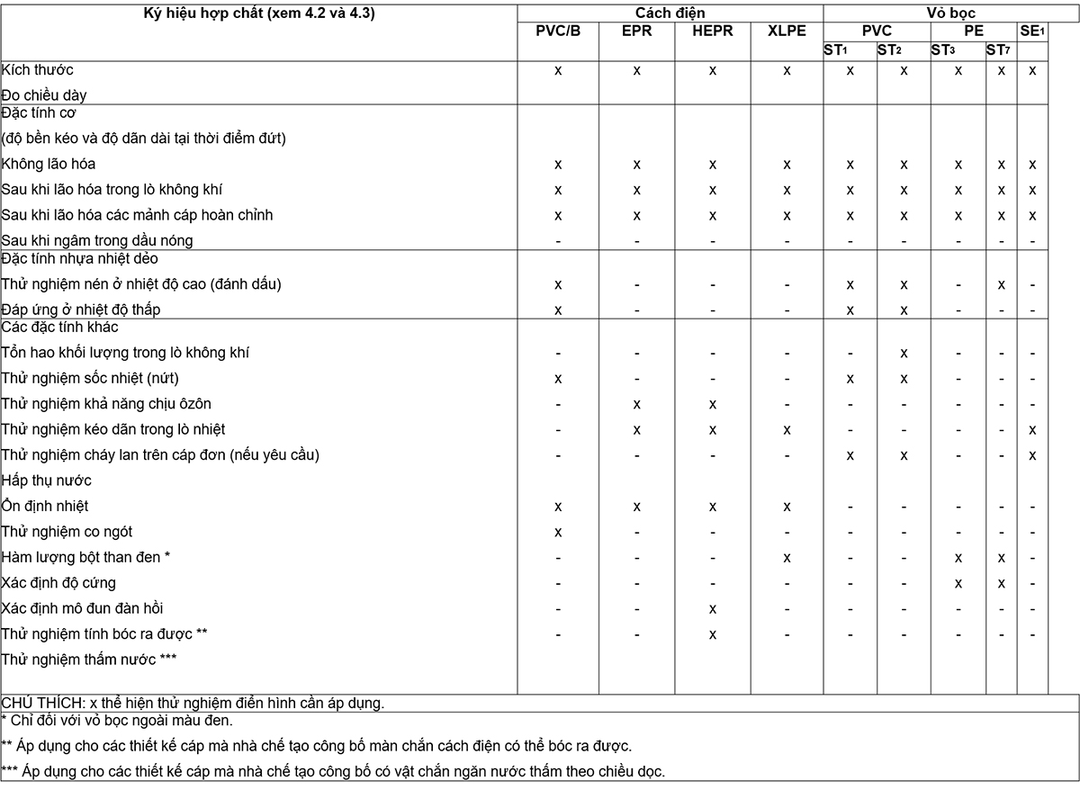
Non-electrical type tests required in this standard are given in Table 16.
19.1 Measurement of insulation thickness
19.1.1 Sampling
A sample shall be taken from the insulated cable core.
19.1.2 Process
The measurement shall be carried out as described in 8.1 of IEC 60811-1-1.
19.1.3 Requests
See 17.5.2.
19.2 Thickness measurement of non-metallic sheath (including extruded separator sheath but not inner sheath)
19.2.1 Sampling
A cable sample must be obtained.
19.2.2 Process
The measurement shall be made as described in 8.2 of IEC 60811-1-1.
19.1.3 Requests
See 17.5.3.
19.2 Test to determine the mechanical properties of insulation before and after aging
19.3.1 Sampling
Sampling and test piece preparation shall be carried out as described in 9.1 of IEC 60811-1-1.
19.3 Aging treatment
The aging treatment is carried out as described in 8.1 of IEC 60811-1-2 under the conditions specified in Table 17.
19.3.3. Stabilization and mechanical testing
Calibration and measurement of mechanical properties shall be carried out as described in 9.1 of IEC 60811-1-1.
19.3.4 Requests
The test results for aged and unaged test pieces shall comply with the requirements given in Table 17.
19.4 Test to determine the mechanical properties of non-metallic enclosures before and after aging
19.4.1 Sampling
Sampling and test piece preparation shall be carried out as described in 9.2 of IEC 60811-1-1.
19.4.2 Treatment of aging
The aging treatment shall be carried out as described in 8.1 of IEC 60811-1-2 under the conditions specified in Table 20.
19.3.3. Stabilization and mechanical testing
Calibration and measurement of mechanical properties shall be carried out as described in 9.1 of IEC 60811-1-1.
19.3.4 Requests
The test results for aged and unaged test pieces shall comply with the requirements given in Table 20.
19.5 Additional aging test on complete cable pieces
19.5.1 General requirements
The purpose of this test is to check that the insulation and non-metallic sheath will not degrade in service due to contact with other components in the cable.
The test applies to all cable types.
19.5.2 Sampling
The sample shall be taken from the complete cable as described in 8.1.4 of IEC 60811-1-2.
19.5.3 Anti-aging treatment
Aging treatment of cable pieces shall be carried out in an air furnace as described in 8.1.4 of IEC 60811-1-2 under the following conditions:
– temperature: higher than the maximum conductor temperature (10 ± 2) °C of the cable in normal operation (see Table 17);
– time: 7 x 24 h.
19.5.4 Mechanical test
The test piece, which is insulation and sheath taken from an aged cable piece, shall be prepared and subjected to the mechanical tests as described in 8.1.4 of IEC 60811-1-2.
19.5.5 Requirements
The difference between the intermediate values of tensile strength and elongation at break after aging and the corresponding values obtained without aging (see 19.3 and 19.4) shall not exceed the applicable values. for the post-aging test in an air furnace specified in Table 17 for insulation and Table 20 for non-metallic enclosures.
19.6 Mass loss test of PVC sheath of class ST2
19.6.1 Procedure
Sampling and testing procedures shall be in accordance with 8.2 of IEC 60811-3-2.
19.6.2 Requests
The test results shall conform to the requirements given in Table 21.
19.7 High-temperature compression test on non-metallic insulation and enclosures
19.7.1 Procedure
The high-temperature compression test shall be carried out in accordance with Clause 8 of IEC 60811-3-1 using the test conditions given in the test method and in Tables 18, 21 and 22. .
19.7.2 Requirements
The test results shall conform to the requirements given in Clause 8 of IEC 60811-3-1.
19.8 Test on PVC insulation and PVC sheath at low temperature
19.8.1 Procedure
The sampling and test procedure shall be in accordance with Clause 8 of IEC 60811-1-4, using the test temperatures specified in Tables 18 and 21.
19.8.2 Requirements
The test results shall conform to the requirements given in Clause 8 of IEC 60811-1-4.
19.9 Crack resistance test of PVC insulation and PVC sheath (thermal shock test)
19.9.1 Procedure
The sampling and test procedures shall be in accordance with Clause 9 of IEC 60811-3-1, using the test temperatures and times according to Tables 18 and 21.
19.9.2 Requirements
The test results shall conform to the requirements given in Clause 9 of IEC 60811-3-1.
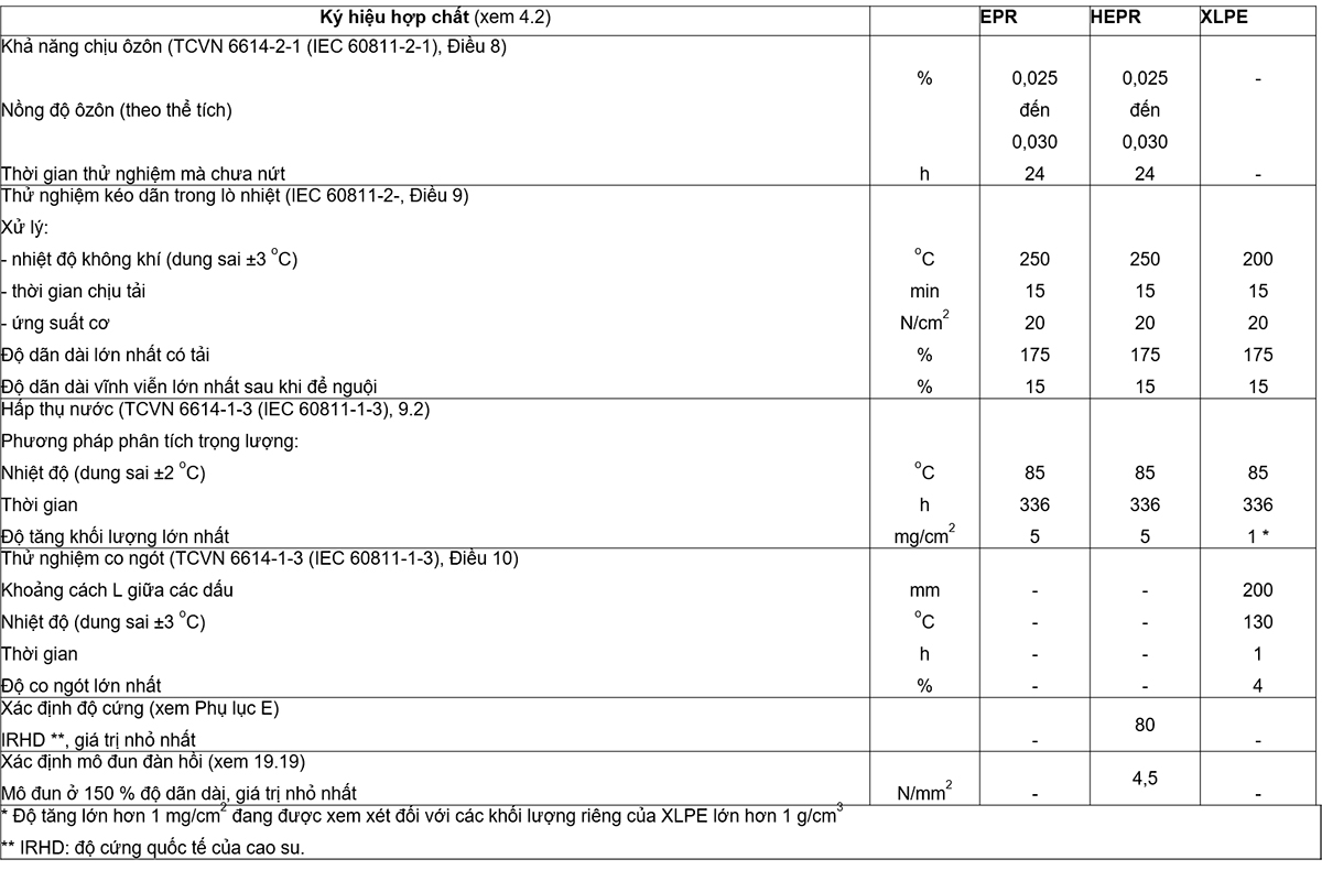
19.10 Ozone resistance test of EPR and HEPR . insulation
19.10.1 Procedure
Sampling and testing procedures shall be carried out in accordance with Clause 8 of IEC 60811-2-1. The ozone concentration and test duration shall be in accordance with Table 19.
19.10.2 Requests
The test results shall conform to the requirements given in Clause 8 of IEC 60811-2-1.
19.11 Heat-furnace stretching test of EPR, HEPR and XLPE insulation and elastomeric sheaths
Sampling and testing procedures shall be carried out in accordance with 17.10 and shall conform to the requirements of 17.10.
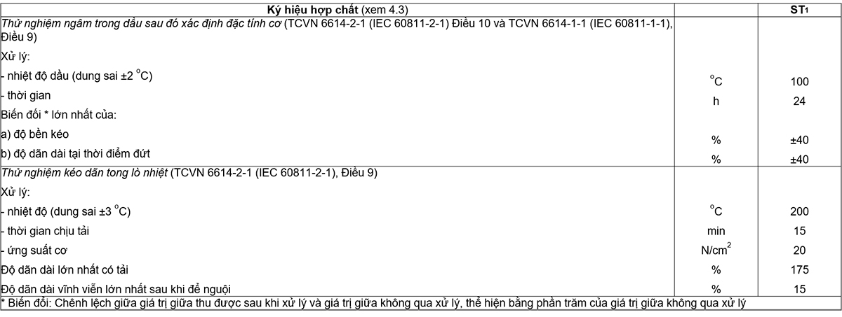
19.12 Oil immersion test for elastomeric sheaths
19.12.1 Procedure
Sampling and testing procedures shall be carried out in accordance with Clause 10 of IEC 60811-2-1, using the conditions given in Table 23.
19.12.2 Requests
The test results shall conform to the requirements given in Table 23.
19.13 Water absorption test of insulation
19.13.1 Procedure
Sampling and testing procedures shall be carried out in accordance with 9.1 or 9.2 of IEC 60811-1-3, using the conditions specified in Tables 18 or 19 respectively.
19.13.2 Requests
The test results shall conform to the requirements given in Tables 18 or 19.
19.14 Fire spread test on a cable
This test is applicable only to cables sheathed with compounds ST1, ST2 or SE1 and is carried out on these cables only when special requirements are required.
The test method and requirements are as specified in IEC 60332-1-2.
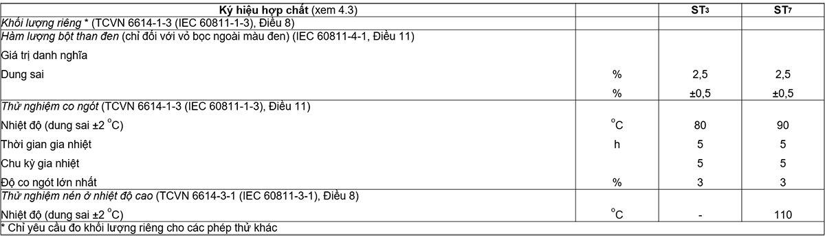
19.15 Measurement of carbon black powder content of black PE outer sheath
19.15.1 Procedure
Sampling and testing procedures shall be carried out in accordance with Clause 11 of IEC 60811-4-1.
19.15.2 Requests
The test results shall conform to the requirements given in Table 22.
19.16 XLPE . insulation shrinkage test
19.16.1 Procedure
Sampling and testing procedures shall be carried out in accordance with Clause 10 of IEC 60811-1-3 under the conditions specified in Table 19.
19.16.2 Requests
The test results shall conform to the requirements given in Table 19.
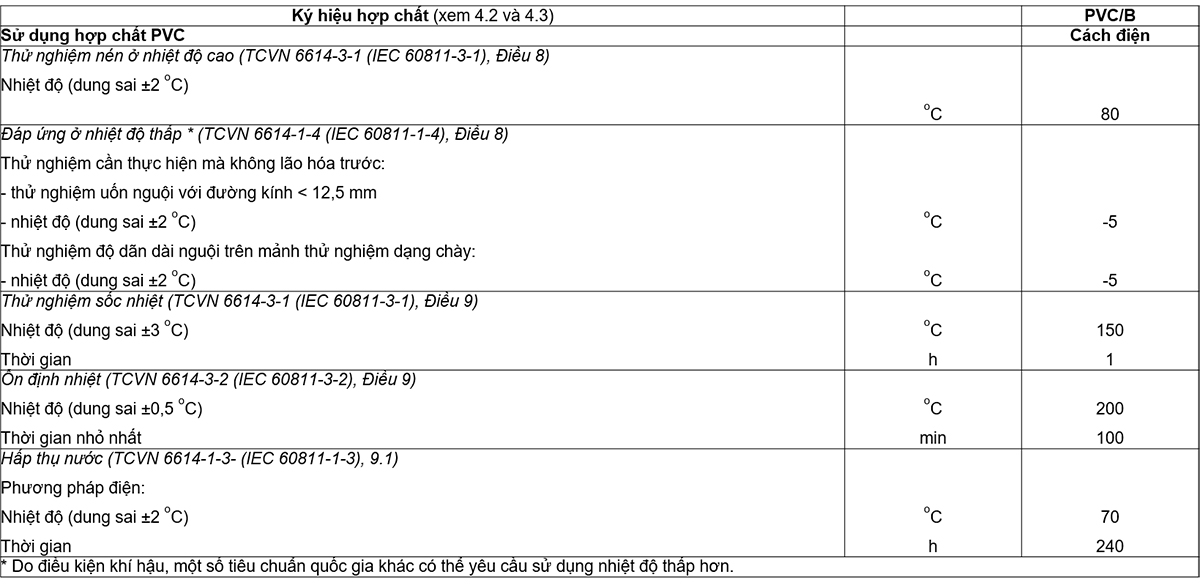
19.7 Thermal stability test for PVC insulation
19.7.1 Procedure
Sampling and testing procedures shall be carried out in accordance with Clause 9 of IEC 60811-3-2 under the conditions specified in Table 18.
19.17.2 Requirements
The test results shall conform to the requirements given in Table 18.
19.18 Determination of the stiffness of HEPR . insulation
19.18.1 Procedure
Sampling and testing procedures shall be carried out in accordance with Annex E.
19.18.2 Requirements
The test results shall conform to the requirements given in Table 19.
19.19 Determination of elastic modulus of HEPR . insulation
19.19.1 Procedure
Sampling, test piece preparation and test procedure shall be carried out in accordance with Clause 9 of IEC 60811-1-1.
The required loads shall be measured to obtain an elongation of 150 %. The corresponding stress is calculated by dividing the measured load by the cross-sectional area of the unstretched test piece. The stress-to-extension ratios shall be determined to obtain elastic moduli at 150 % elongation.
The modulus of elasticity shall be the middle value.
19.19.2 Requirements
The test results shall conform to the requirements given in Table 19.
19.20 Shrinkage test for PE . outer sheath
19.20.1 Process
Sampling and testing procedures shall be carried out in accordance with Clause 11 of IEC 60811-1-3 under the conditions specified in Table 22.
19.20.2 Requests
The test results shall conform to the requirements given in Table 22.
19.21 Peelability test for insulating screens
This test shall be performed when the manufacturer declares the extruded semiconductor insulating screen to be peelable.
19.21.1 Procedure
The test shall be made in triplicate on both the unaged and the aged samples, using three separate samples of cable or a piece of cable at three locations around the circumference, spaced approximately 120° apart.
A core length of at least 250 mm shall be obtained from the cable to be tested before and after aging in accordance with 19.5.3.
Make two cuts in the extruded semiconductor insulating screen of each sample, axially from one end to the other, and radially into the insulation, the cuts (10 ± 1) mm apart and parallel. parallel to each other.
After removing approximately 50 mm of a 10 mm wide ribbon by pulling it parallel to the core (i.e. an angle of approximately 180°, the core shall be mounted vertically on the tensile testing machine with one end of the core is held in one clamp and a 10 mm wide ribbon is held in the other.
The force to peel a 10 mm wide strip from the insulation to remove a segment of at least 100 mm shall be measured with a peel angle of approximately 180° and a tensile rate of (250 ± 50) mm/min.
The test shall be carried out at a temperature of (20 ± 5) °C.
For unaged and aged samples, the peel force value shall be recorded continuously.
19.21.2 Requests
The force required to peel the extruded semiconductor screen from the insulation shall be not less than 4 N and not more than 45 N before and after aging.
The insulating surface shall be undamaged and no trace of a semiconductor screen shall remain on the insulation.
19.22 Waterproof test
The water penetration test shall be applied to cable designs where the manufacturer declares that the cable has a longitudinal waterproof barrier. This test is designed to meet the requirements of underground cables and is not intended to be applied to cables constructed for use as underwater cables.
The test applies to the following cable designs:
a) there is a barrier to prevent longitudinal water infiltration in the area of the metal layers;
b) there is a barrier to prevent longitudinal water infiltration along the conductor.
Equipment, sampling and testing procedures shall be in accordance with Annex F.
20 Electrical test after installation
The post-installation test is performed when the installation of cables and accessories has been completed.
The d.c. electrical oversheath test according to 20.1 is recommended and, if required, the insulation test according to 20.2. For installations where only the enclosure test according to 20.1 is to be carried out, the quality assurance procedure during the installation of the accessory may be substituted for this insulation test, by agreement between manufacturer and user. buying.
20.1 Outer enclosure d.c. voltage test
The voltage level and time specified in Clause 5 of IEC 60229 shall be applied between each metal enclosure or metal screen and earth.
For the test to be valid, good soil contact should be made on all outer surfaces of the enclosure. The conductive layer on the outer sheath can help in this regard.
20.2.1 AC test
By agreement between purchaser and contractor, the a.c. voltage test at power frequency according to point a) or point b) below may be used:
a) test for 5 min at the phase-to-phase voltage of the system placed between the conductor and the metal screen/enclosure;
b) tested for 24 h at the normal operating voltage of the system.
20.2.2 d.c. test
As an alternative to the a.c. test, a d.c. test voltage of 4 Uo may be applied for 15 min.
NOTE 1 The d.c. test can be hazardous to the insulation system under test. Other testing methods are under consideration.
NOTE 2 For existing installations, a lower voltage and/or shorter duration may be used. Values should be agreed, taking into account the life, the environment, the history of the disruptive discharge and the purpose of the test.
Appendix A
(rule)
A hypothetical calculation method for determining the dimensions of the protective coating
The thickness of the cable sheaths, such as sheath and armor, is usually related to the nominal diameter of the cable according to the “gradient”.,
Sometimes this causes some problems. The nominal calculated diameters are not necessarily the same as the actual values achieved in production. In extreme cases, doubts may arise if the thickness of the coating does not correspond to the actual diameter, because the calculated diameters differ slightly. Differences in the size of profiled conductors between different manufactures and calculations give rise to differences in rated diameters and thus may result in differences in the thickness of the coating used on top. a basic design of the cable.
To eliminate these problems, a hypothetical calculation method must be used. The essence of this method is to ignore the shape and degree of compaction between the conductors, and calculate only the assumed diameter using a formula based on the cross-sectional area of the conductor, the nominal thickness of insulation and number of cores. The thickness of the sheath and other coatings are then related to the assumed diameter through formulas or tables. The method of calculating the hypothetical diameter is precisely specified and there is no clarity as to the thickness of the coating that should be used as they are not subject to slight variations in manufacturing practice. This will standardize the cable design, the thickness of which is pre-calculated and specified for each conductor cross-section.
The assumed calculation method is only used to determine the dimensions of the sheaths and sheaths of the cables. This method cannot be used as a substitute for the calculation of the actual diameter required for practical purposes, which must be done separately.
A.1 General requirements
The hypothetical method below, for calculating different sheath thicknesses in a cable, has been adopted to ensure that any differences that may arise in independent calculations are ignored, for example as due to the assumption of conductor dimensions and the inevitable difference between the nominal and actual diameters achieved.
All thickness and diameter values will be rounded to the first decimal according to the rules in Annex C.
Holding tape, e.g. anti-helical tape on armor, if not thicker than 0.3 mm, is omitted from this calculation method.
A.2 Method
A2.1 Conductor
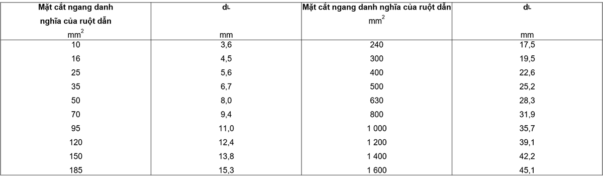
The assumed diameter (dL) of the conductor, excluding shape and tightness, for each of the nominal cross-sections given in Table A.1.
A.2.2 Core
The assumed diameter Dc of any core is determined as follows:
a) for cables with cores without a semiconductor screen:
Dc = dL + 2ti
b) for cables with a semiconductor screen core:
Dc = dL + 2ti + 3.0
where ti is the nominal thickness of the insulation, in millimetres (see Tables 5 to 7).
If a metallic screen or concentric conductor is used, further additions shall be made in accordance with A.2.5.
A.2.3 Diameter of arranged cores
The assumed diameter of the arranged cores (Df) is given by:
Df = k Dc
where the assembly factor k is 2.16 for a three-core cable.
A.2.4 Inner coating
The assumed diameter of the inner covering (Leather) is determined by:
Skin = Df + 2 tB
Inside:
tb = 0.4 mm for the assumed diameter of arranged cores (Df) up to and including 40 mm;
ta = 0.6 mm for Df greater than 40 mm.
The assumed values of tB apply to:
a) three-core cable:
– whether or not there is an inner covering;
– whether the inner coating is extruded or wound;
unless a separator conforming to 12.3.3 is used in place of the inner covering or in addition to the inner covering, A.2.7 shall apply.
b) single-core cable:
when an inner wrap is used regardless of extrusion or wrapping.
A.2.5 Concentric conductors and metal screens
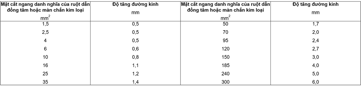
The increase in diameter due to concentric conductors or metallic screens is given in Table A.2.
If the cross-section of a concentric conductor or metallic screen lies between the two values given in the table above, the increase in diameter is chosen for the value of the larger cross-section of the two.
If a metal screen is used, the cross-sectional area of the screen to be used in the table above shall be calculated in the following manner:
a) ribbon screens:
cross-sectional area = nt x tt x wt
Inside
nt is the number of bands;
tt is the nominal thickness of an individual tape, in millimetres;
wt is the nominal width of an individual ribbon, in millimeters.
Where the total thickness of the screen is less than 0.15 mm, the increase in diameter shall be zero:
– for tape-wrap screens made of two tapes or one tape with overlapping sections, the total thickness being twice the thickness of one tape;
– for longitudinally wound tape screens:
• if the overlap is less than 30%, the total thickness is the thickness of the tape;
• if the overlap is greater than or equal to 30 %, the total thickness is twice the thickness of the tape.
b) rope screen (reverse spiral, if any)
cross-sectional area =  nh x th x wh
Inside
nw is the number of ropes;
dw is the diameter of a single wire, in millimetres;
h is the number of spirals in the opposite direction;
th is the thickness of a counter-helix, in millimetres, if more than 0.3 mm;
wh is the width of one helix in the opposite direction, in millimeters.
A.2.6 Lead sheath
The assumed diameter of the lead sheath (Dpb) is given by:
Dpb = Dg + 2tpb
Inside:
Dg is the assumed diameter under the lead sheath, in millimeters;
Tpb is the thickness in 12.1, in millimetres.
A.2.7 Separation sheath
The assumed diameter of the separator sheath (Ds) is given by:
Ds = Du + 2ts
Inside:
Du is the assumed diameter below the separator sheath, in millimetres;
ts is the thickness in millimeters according to 13.3.3.
A.2.8 Stacked wrap liners
The assumed diameter of the stacked wrap liner (Dlb) is given by:
Dlb = Dulb + 2tlb
Inside:
Dulb is the assumed diameter below the stacked wrap lining, in millimeters;
tlb is the thickness of the stacked wrap liner, i.e. 1.5 mm according to 13.3.4.
A.2.9 Additional lining for cables with ribbon armor (wrap on inner sheath)
A.2.10 Armor
The assumed diameter of the armor (Dx) is determined:
a) for flat wire or round wire armor:
Dx = DA + 2 tA + 2 tw
Inside:
DA is the diameter under the armor, in millimeters;
tA is the thickness or diameter of the armor wire, in millimetres;
tW is the thickness of the counter-helix, if any, in millimetres, if greater than 0.3 mm.
b) for double-wrap armor:
Dx = DA + 4 tA
Inside:
DA is the diameter under the armor, in millimeters;
tA is the thickness of the armor tape, in millimeters.
(refer)
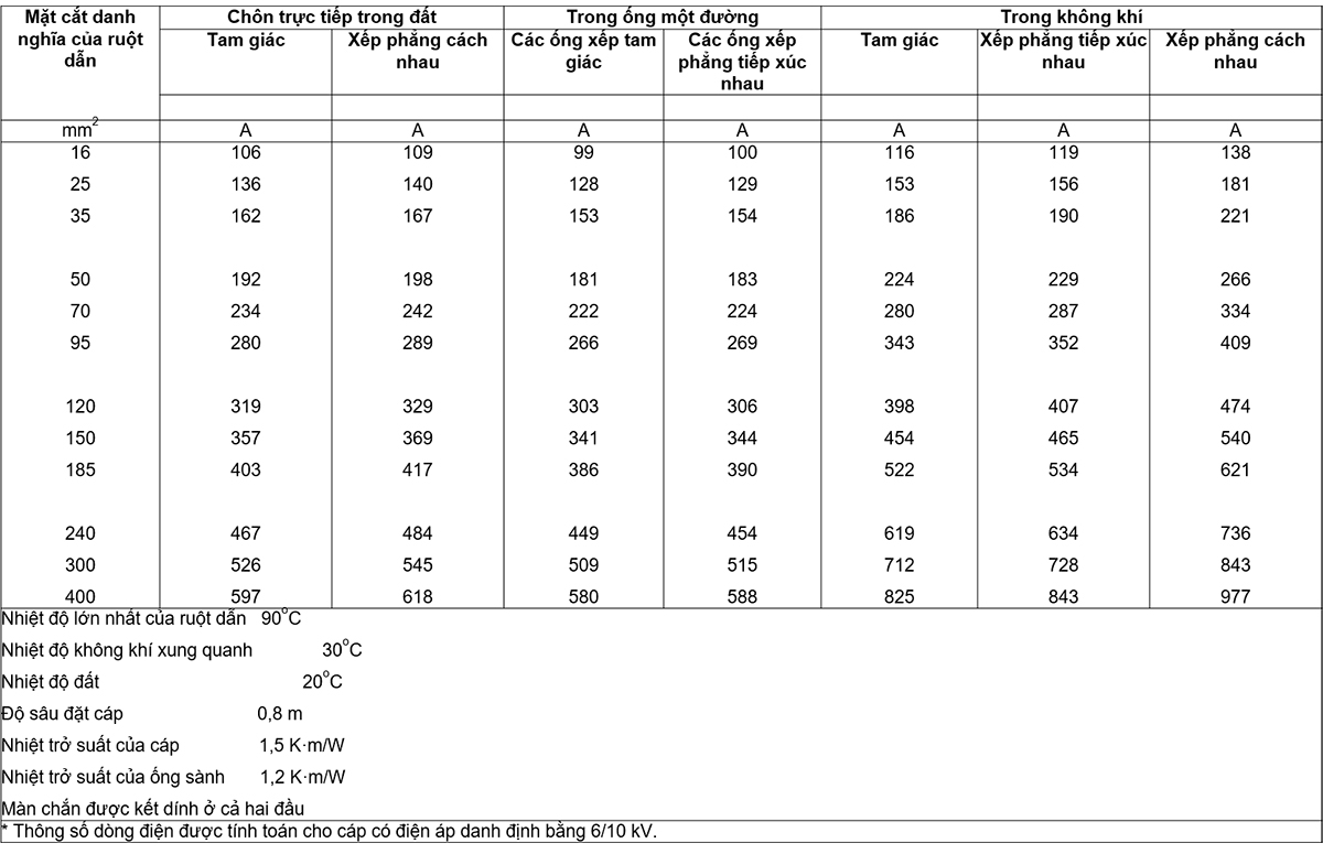
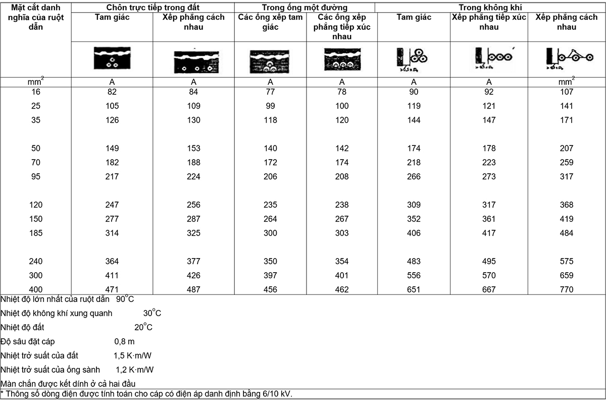
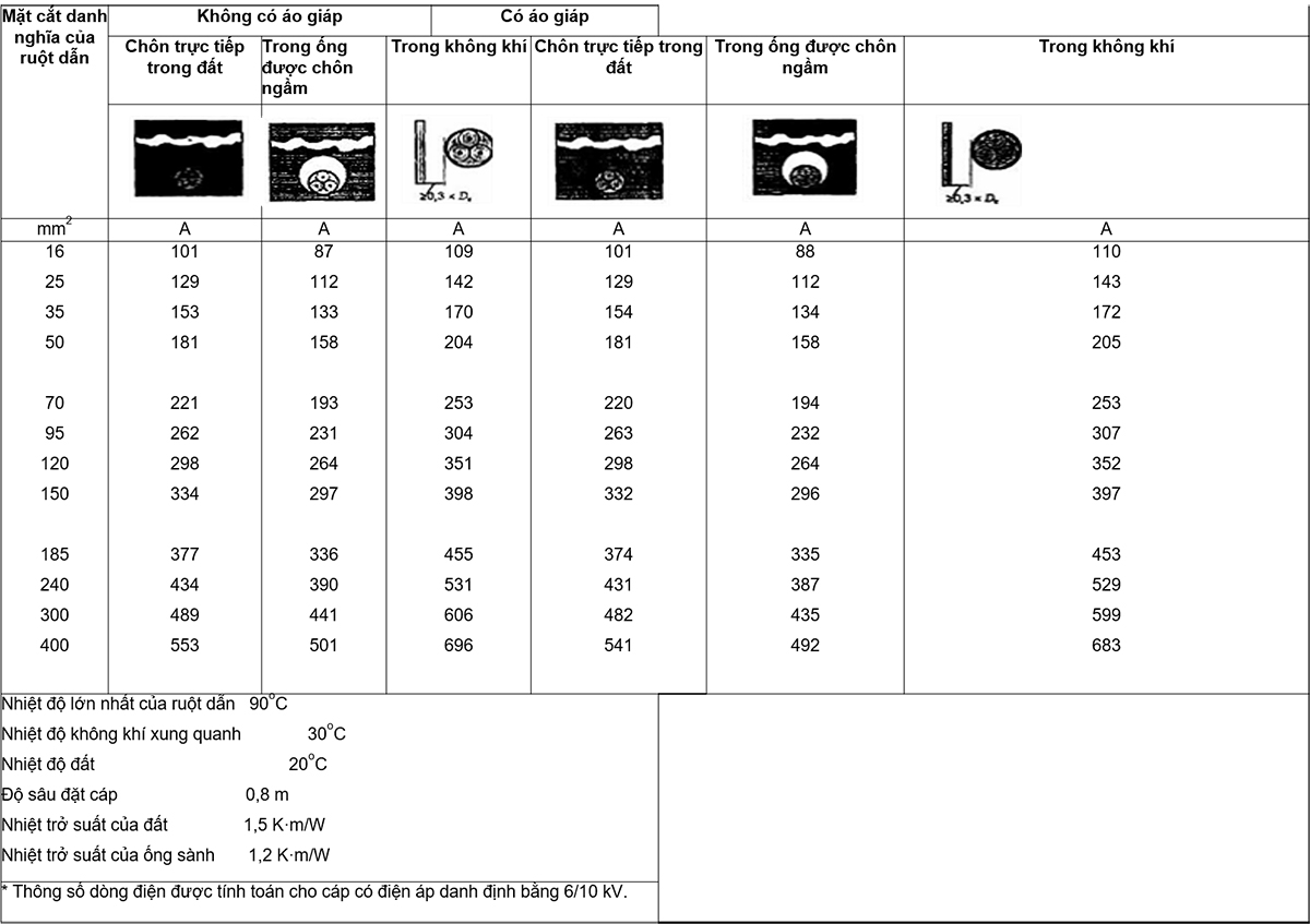
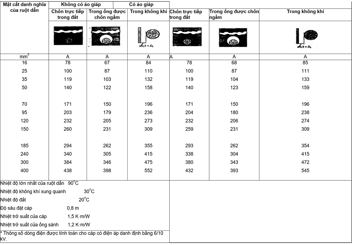
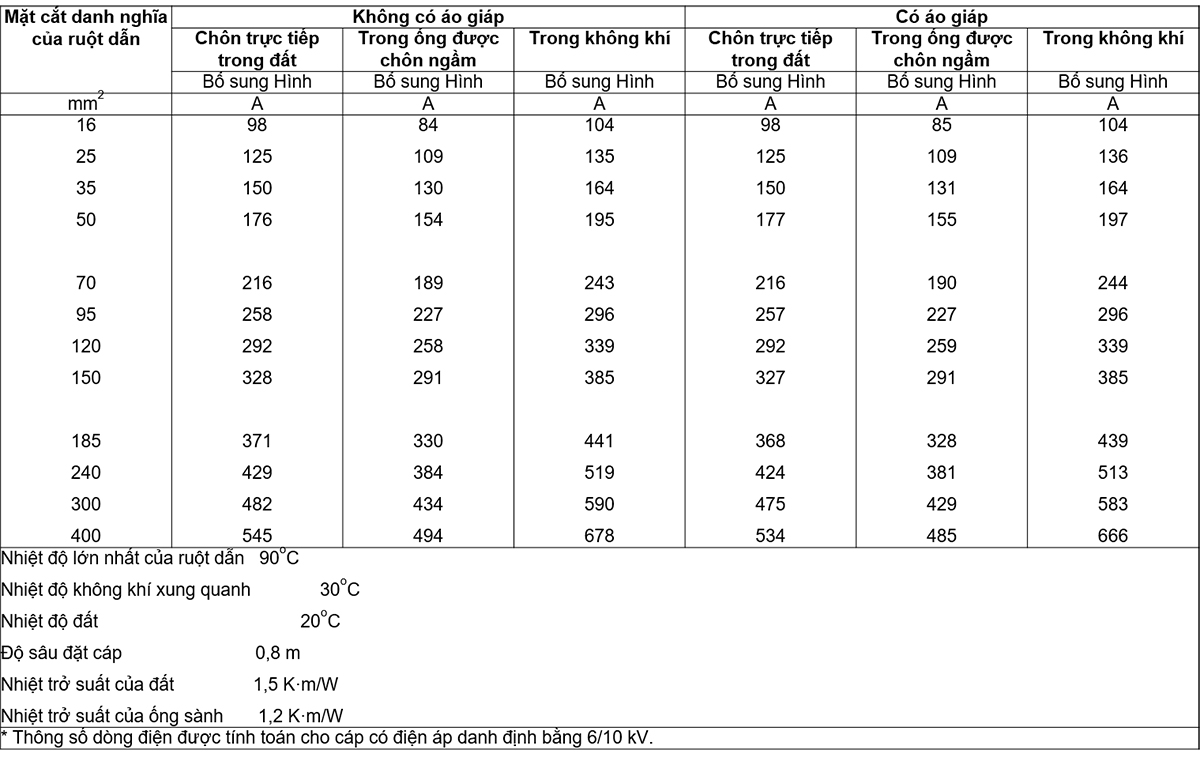
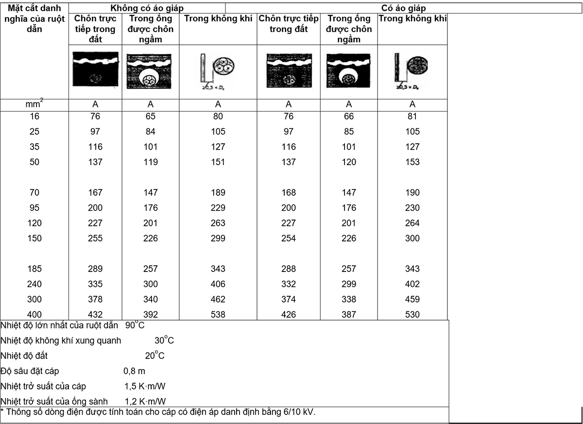
Tabulated continuous current ratings for cables with extruded insulation having rated voltages from 3,6/6 kV to 18/30 kV.
B.1 General requirements
This annex deals exclusively with steady-state continuous-current ratings for single-core and three-core cables with extruded insulation. The current ratings tabulated in this annex have been calculated for cables having a rated voltage of 6/10 kV and of construction as detailed in Clause B.2.
These parameters are applicable to cables of similar construction in the voltage range from 3.6/6 kV to 18/30 kV.
Several parameters such as the cross-sectional area of the screen and the thickness of the sheath have an influence on the performance of large cables. In addition, the method of screen bonding is also taken into account in the specification of single-core cables.
The tabulated current rating has been calculated using the method shown in IEC 60287.
NOTE 1 For the cyclic current rating, see IEC 60853.
NOTE 2 For short-circuit temperature limits, see IEC 60986.
B.2 Cable structure
Cable construction and dimensions for which current ratings are tabulated are based on construction and dimensions given in this standard. The construction and dimensions used are not related to country specific designs but reflect different cable models. Armored three-core cables are assumed to have flat-wire armor and single-core cables are assumed to be unarmored. All cables have copper ribbon core screen except single core XLPE insulated cable with copper wire screen. The nominal cross-sectional area of the screen for cable samples is given in Table B.1.

The outer sheath is taken as polyethylene for single-core cables and PVC for three-core cables.
B.3 Temperature
The highest conductor temperature for the calculation of the tabulated cable ratings is 90 °C.
The standard ambient temperature is assumed as follows:
– for cables in the air: 30 oC
– for cables buried underground, directly in the ground or in underground pipes: 20 oC
Correction factors for other ambient air temperatures are given in Tables B.10 and B.11.
The current rating for cables in the air does not take into account the rise due to solar or other infrared radiation, if any. In the case of cables subjected to this radiation, the current rating should be calculated according to the methods specified in IEC 60287.
B.4 Thermal resistivity of soil
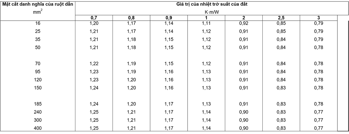
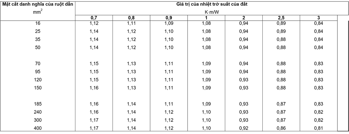
The tabulated current parameters for cables laid in pipes or buried directly in the ground are related to the thermal resistivity of the soil of 1.5 Km/W. Information on similar soil heat resistivity in different countries is given in IEC 60287-3-1. The correction factors for different values of thermal resistivity are given in Tables B.14 to B.17.
Assuming that the soil properties are uniform, the possibility of moisture migration is ignored, which could lead to the formation of a heat resistive zone around the cable. If partial drying of the soil is foreseen, the allowable current rating should be determined by the method given in IEC 60287.
B.5 Installation method
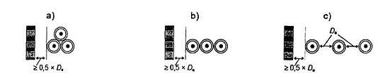
The current ratings given in the table are for cables installed under the following conditions:
B.5.1 Single-core cable in the air
Cables are considered to be located at least 0.5 times the cable diameter from any vertical surface and are mounted on a cantilever or ladder as follows:
a) three cables laid in triangular contact throughout the length of the cable;
b) three cables laid horizontally in contact with each other throughout the length of the cable;
c) three cables laid in a horizontal plane one diameter apart.
B.5.2 Direct buried single-core cable
The current ratings are given for cables directly buried in the ground at a depth of 0.8 m under the following conditions:
a) three cables laid in triangular contact throughout the length of the cable;
b) three cables laid in a horizontal plane one cable diameter apart, De.
The cable burial depth is measured to the axis of the cable or the center of a group of three cables laid out in the form of a triangle.
B.5.3 A core in a crock pot
The current ratings are given for cables buried in earthenware pipes placed in the ground at a depth of 0,8 m with one cable in each tube:
a) three cables in three conduit laid in triangular contact throughout the length of the conduit;
b) three cables laid in a horizontal plane, the tubes in contact throughout the length of the conduit.
Pipes are considered to be earthenware having an inside diameter of 1.5 times the outside diameter of the cable and a wall thickness of 6% of the inside diameter of the tube. The current rating is based on the assumption that the tube is filled with air. If the conduit contains another material such as bentonite, it is generally acceptable to use the current ratings for direct buried cables.
The tabulated current specification is applicable to cables in conduit with a diameter of 1.2 to 2 times the outside diameter of the cable. For this diameter range, the variation of the current rating is less than 2 % of the tabulated value.
B.5.4 Three-core cable
The current ratings are given for three-core cables installed under the following conditions:
a) a cable placed in the air at least 0.3 times the cable diameter from any vertical surface;
b) a cable buried directly in the ground at a depth of 0,8 m;
c) a cable laid in an earthenware conduit whose diameter is calculated in the same way as for single-core cables laid in a conduit. The buried depth of the pipe is 0.8 m.
B.6 Adhesion of screens
All tabulated current ratings for single-core cables are assumed to be tightly bonded cable screens, i.e. bonded at both ends of the cable.
B.7 Carrying load for cable
The tabulated current ratings relate to balanced three-phase load-carrying circuits at rated frequency of 50 Hz.
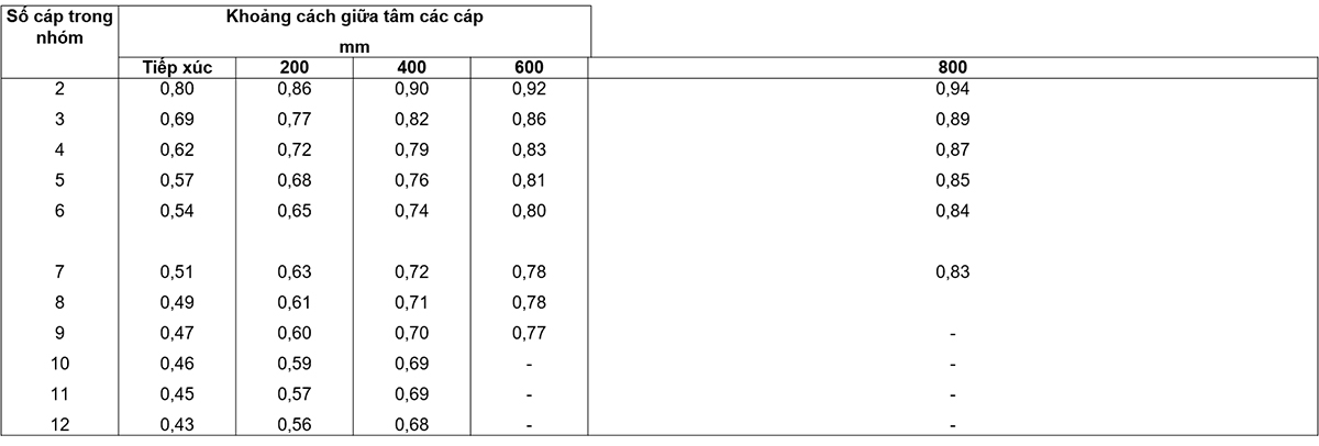
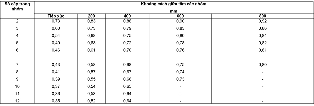
B.8 Scale factor for grouping circuits
The tabulated current ratings apply to a set of three single-core cables or one three-core cable forming a three-phase circuit. When a large number of circuits are installed close together, the current rating should be reduced by an appropriate factor taken from Tables B.18 to Table B.23.
These factors should also apply to groups of parallel cables forming the same circuit. In these cases, attention should also be paid to the cable arrangement to ensure that the load carrying current is evenly distributed among the parallel cables.
B.9 Adjustment factor
The correction factors given in Tables B.10 to B.23 for temperature, mounting and grouping conditions are average values over a range of conductor sizes and cable types. For specific cases, the correction factor can be calculated using the methods in IEC 60287-2-1.


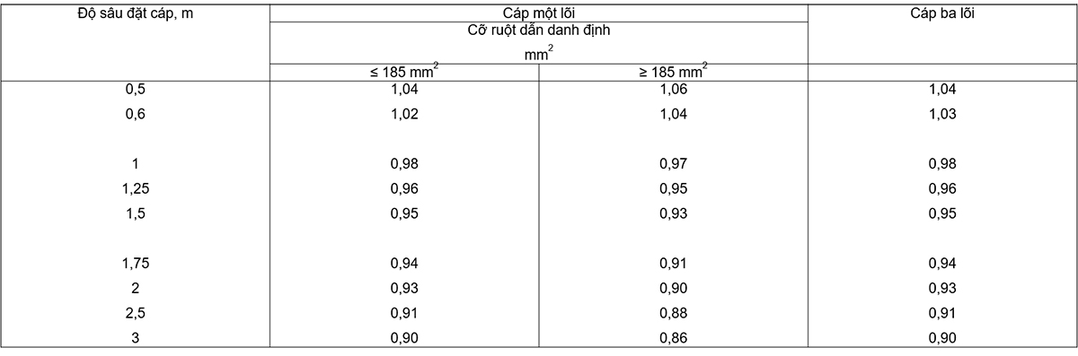

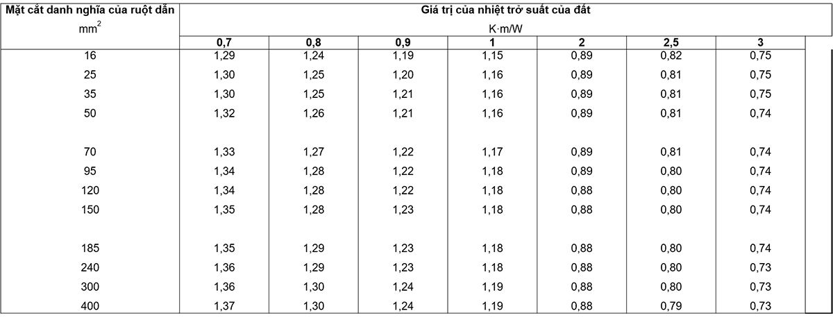

NOTE 1 The values in the table are averages for the cables and range of conductor sizes under consideration. The difference between the values is generally less than 5 %.
NOTE 2 The factors apply to a group of single-layer cables as shown above and do not apply when cables are installed in more than one contact layer. Values for installations can be significantly lower and should be determined by an appropriate method.
NOTE 3 The given value for vertical distances between trays is 300 m and a minimum of 20 mm between tray and wall. For closer distances, the coefficient should be reduced.
NOTE 4 The given value for the horizontal distance between the trays is 225 mm with the trays mounted back to back. For closer distances, the coefficient should be reduced.
Appendix C
(rule)
C.1 Rounding for hypothetical calculation method
The following rules apply when rounding numbers during the calculation of the assumed diameter and the determination of the dimensions of the component classes in accordance with Annex A.
At any step, when the calculated value has more than one decimal place, the value must be rounded to one decimal, i.e. to the nearest 0.1 mm. The assumed diameter at each step shall be rounded to the nearest 0.1 mm and when used to determine the thickness or dimensions of an outer layer, this diameter shall be rounded before being used in formulas or tables. suitable. The thickness is calculated from the value of the assumed diameter rounded off in turn to 0.1 mm as specified in Annex A.
To illustrate the above rules, give the following practical examples:
a) when the digit at the second decimal place before rounding is 0, 1, 2, 3 or 4, the digit at the first decimal place is unchanged (round down)
Eg:
2.12  2.1
2.1
2.449 2.4
25.0478 25.0
b) when the second decimal place before rounding is 9, 8, 7, 6 or 5, the digit in the first decimal place is increased by one (rounded up).
Eg:
2.17 2.2
2.453 2.5
30,050 30.1
C.2 Rounding off numbers for other purposes
For purposes other than those mentioned in C.1, values may be rounded to more than one decimal place. This can happen, for example, when calculating the average of several measurements or calculating the minimum using the wrong percentage for a given nominal value. In these cases, rounding will be rounded to the decimal places specified in the respective clauses.
The method of rounding numbers is:
a) if after the last digit retained, before rounding, are the numbers 0, 1, 2, 3 or 4, the last digit retained is preserved (rounded down).
b) if the last digit retained, before rounding, is 9, 8, 7, 6 or 5, then the last digit retained will be incremented by one (rounded up).
Eg:
2.449 2.45 round to two decimal places
2,449 2.4 rounded to decimal
25.0478 25,048 round to three decimal places
28.0478 25.05 round to two decimal places
25.0478 25.0 rounded to one decimal.
(rule)
Method of measuring the resistivity of a semiconductor screen
Each test piece shall be prepared from a complete sample of cable 150 mm long.
The conductor screen test piece shall be prepared by cutting the core sample in half lengthwise, removing the conductor and separator, if any (see Figure D.1a). The insulating screen test piece shall be prepared by removing all coatings from the core sample (see Figure D.1b).
The procedure for determining the mass resistivity of the screen is as follows:
Four silver-painted electrodes A, B, C and D (see Figures D.1a and D.1b) shall be applied to the semiconductor surfaces. The two electrode bodies B and C shall be 50 mm apart and the two current electrodes, A and D, shall be at least 25 mm outward from the electrode potentials.
The connection to the electrodes shall be made with suitable clamps. When connecting conductor screen electrodes, it shall be ensured that the clamps are insulated from the insulating screen on the outer surface of the test specimen.
The assembly shall be placed in an oven which has been preheated to the specified temperature and, after a period of at least 30 min, the resistance between the electrodes shall be measured by means of a circuit, the capacity of which shall not be exceed 100 mW.
After electrical measurements, the outer diameter of the conductor screen and the insulating screen and the thickness of the conductor screen and the insulating screen shall be measured at ambient temperature, each diameter being the average of six measurements made on the sample shown in Figure D.1b.
The mass resistivity ρ, in ohms, is calculated as follows:
a) conductor screen

Inside
ρc is the mass resistivity, in ohms meter;
Rc is the measured resistance, in ohms;
Lc is the distance between electrode potentials, in meters;
Dc is the outside diameter of the conductor screen, in metres;
Tc is the average thickness of the conductor screen, in metres.
b) insulating screen

Inside:
ρi is the mass resistivity, in ohms meter;
Ri is the measured resistance, in ohms;
Li is the distance between electrode potentials, in meters;
Di is the outside diameter of the insulating screen, in metres;
Ti is the average thickness of the insulating screen, in metres.
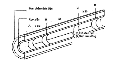
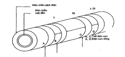
Appendix E
(rule)
Determination of the stiffness of HEPR . insulation
E.1 Test piece
The test piece shall be a sample of the cable complete with all of the HEPR insulation under test, carefully removed. Alternatively, an insulating core sample can be used.
E.2 Test procedure
Tests are carried out in accordance with ISO 48 with the exceptions indicated below.
E.2.1 Surface of large radius of curvature
The test device, in accordance with ISO 48, shall be constructed so that it can rest firmly on the HEPR insulation and allow the feet of the compression tool and the marker to come into vertical contact with this surface. This is done in one of two ways:
a) the tool is fitted with movable pins in universal joints so that they self-adjust on curved surfaces;
b) the base of the measuring instrument is fitted with two parallel bars A and A’ separated by a distance depending on the curvature of the surface (see Figure E.1).
The above methods can be used on surfaces with radius of curvature as small as 20 mm.
When the thickness of the HEPR insulation to be tested is less than 4 mm, a measuring instrument as described in the method in ISO 48 shall be used for thin and small test pieces.
E.2.2 Surface of small radius of curvature
On surfaces where the radius of curvature is too small for the procedures described in E.2.1, the test piece shall be supported on the same rigid base as the test tool in a manner that minimizes overall displacement displacement of the HEPR insulation when increasing the marking force is applied to the marker and so that the marker is vertically above the axis of the test piece. Suitable procedures are as follows:
a) by placing the test piece in a groove or chute in a metal mold (see Figure E.2a);
b) by placing the conductor ends of the test piece in the V-block (see Figure E.2b).
The minimum radius of curvature of the surface to be measured according to the above methods shall be at least 4 mm.
For smaller radii, a measuring instrument as described in the method in ISO 48 shall be used for thin and small test pieces.
E.2.3 Stability and test temperature
The minimum time between production, i.e. vulcanization and testing shall be 16 h.
The test shall be carried out at a temperature of (20 ± 2) °C and the test pieces shall be maintained at this temperature for at least 3 h immediately prior to the test.
E.2.4 Number of measurements
One measurement shall be made at each of the three or five different points distributed around the test piece. The middle value of the results is taken as the hardness of the test piece, recorded in the report to the nearest whole number in terms of international rubber hardness (IRHD).
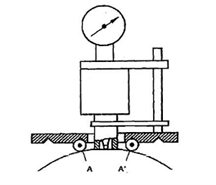
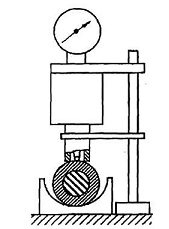
Appendix F
(rule)
F.1 Test piece
Complete samples of cables at least 6 m in length which have not been subjected to any of the tests described in Clause 18 shall be subjected to the bending test as described in 18.1.4 without further partial discharge tests.
Cut a length of cable 3 m from the cable sample that has been subjected to the above bending test and lay it horizontally. A segment approximately 50 mm wide shall be removed from the center of this cable segment. This ring includes all layers outside the insulating screen. In the case of conductors declared to have a barrier, this ring shall also have all layers outside the conductor.
If the cable contains intermittent barriers that prevent longitudinal water infiltration, the sample shall contain at least two of these barriers, one of which is removed from between the barriers. In this case, the average distance between the obstructions on these cables should be specified and the cable sample length shall be determined accordingly.
Surfaces shall be cut so that common surfaces intended to be longitudinally watertight are readily exposed to water. Common surfaces that are not designed to be longitudinally watertight shall be sealed with suitable material or have any outer coverings removed.
Examples of common surfaces that are not longitudinally watertight include:
– when only the conductors of the cable are shielded;
– the common surface between the outer enclosure and the metal enclosure.
Arrange suitable equipment (see Figure F.1) to allow a tube of at least 10 mm diameter to be placed vertically above the exposed ring and to be attached to the surface of the enclosure. A tight connection where the cable exits the equipment shall not create mechanical stress on the cable.
NOTE The response of certain barriers to longitudinal water penetration may depend on the composition of the water (e.g. pH, ion concentration). Normal tap water should be used for this test, unless otherwise specified.
F.2 Test
The tube is filled with water for 5 min at an ambient temperature of (20 ± 10) °C such that the height of the water in the tube is 1 m above the center of the cable (see Figure F.1). Samples should be kept for 24 h.
The sample is then subjected to 10 heating cycles by passing current through the conductor, until the conductor is brought to a steady temperature 5 °C to 10 °C above the maximum conductor temperature during operation. normal and does not reach 100°C.
The duration of the heating cycle shall be 8 h. The conductor temperature shall be maintained within the specified temperature limits for at least 2 h of each heating period. It shall then be allowed to cool naturally for at least 3 h.
The height of the water must be maintained at 1 m.
NOTE No voltage is applied during the test, if a dummy cable is connected in series with the cable under test, the temperature is measured directly across the conductor of this dummy cable.
F.3 Requirements
During the test period, water shall not escape from the ends of the test piece.
REFERENCES DIRECTIONS
[1] IEC 60287 (all parts), Electric cables – Calculation of the current rating [2] TCVN 5935-1 (IEC 60502-1) Electrical cables with extruded insulation and cable accessories with rated voltage from 1 kV (Um = 1.2 kV) to 30 kV (Um = 36 kV) – Part 1: Cables with a rated voltage of 1 kV (Um = 1.2 kV) and 3 kV (Um = 3.6 kV) [3] IEC 60853 (all parts), Calculation of the cyclic and emergency current rating of cables cable).TABLE OF CONTENTS
Preface
1 Scope of application
2 References
3 Terms and definitions
4 Voltage symbols and materials
5 Conductors
6 Insulation
7 Curtains
8 Three-core cable assembly, inner sheath and filler
9 Metallic layers for single-core and three-core cables
10 Metal screens
11 Concentric conductors
12 Metal cover
13 Metal Armor
14 Outer sheath
15 Test conditions
16 Regular testing
17 Sample test
18 Electrical type test
19 Non-electrical type test
20 Electrical test after installation
Annex A (normative) – Presumptive calculation method for determining the size of the protective covering
Annex B (for reference) – Tabulated continuous current ratings for cables with extruded insulation having rated voltages from 3.6/6 kV to 18/30 kV
Appendix C (regulations) – Rounding off
Annex D (normative) – Method for measuring the resistivity of semiconductor screens
Annex E (normative) – Determination of stiffness of HEPR . insulation
Annex F (normative) – Water penetration test.