NATIONAL STANDARDS
TCVN 5935-1 : 2013
IEC 60502-1 : 2009
ELECTRICAL CABLES WITH LAMP INSULATION AND ACCESSORIES FOR Rated VOLTAGE FROM 1kV (Um = 1.2kV) TO 30kV (Um = 36kV) – PART 1: CABLES FOR Rated VOLTAGE 1kV (Um = 1, 2kV) TO 3kV (Um = 3.6kV)
Power with cables extruded insulation and their accessories for rated voltages from 1kV (Um = 1.2kV) up to 30kV (Um = 36kV) – Part 1: Cables for rated voltages of 1kV (Um = 1.2kV) and 3kV (Um = 3.6kV)
Preface
TCVN 5935-1: 2013 and TCVN 5935-2:2013 replace TCVN 5935:1995.
TCVN 5935-1 : 2013 is completely equivalent to IEC 60502-1:2009.
TCVN 5935-1 : 2013 compiled by the Technical Committee for National Standards TCVN/TC/E4 Electrical wires and cables, proposed by the General Department of Standards, Metrology and Quality, and published by the Ministry of Science and Technology.
Set of IEC 60502 Electrical cables with extruded insulation and cable accessories for rated voltages from 1 kV (Um = 1,2kV) to 3kV (Um = 3.6kV), consisting of the following parts:
TCVN 5935-1:2013 (IEC 60502-1:2009), Part 1: Cables for rated voltages of 1 kV (Um = 1.2kV) and 3kV (Um = 3.6kV)
TCVN 5935-2:2013 (IEC 60502-2:2005), Part 2: Cables for rated voltages from 6 kV (Um = 7.2kV) to 30kV (Um = 36kV)
TCVN 5935-4:2013 (IEC 60502-4:2005), Part 4: Test requirements for cable accessories with rated voltages of 6 kV (Um = 7.2kV) and 30kV (Um = 36kV)
ELECTRICAL CABLES WITH LAMP INSULATION AND ACCESSORIES FOR Rated VOLTAGE FROM 1kV (Um = 1.2kV) TO 30kV (Um = 36kV) – PART 1: CABLES FOR Rated VOLTAGE 1kV (Um = 1, 2kV) TO 3kV (Um = 3.6kV)
Power with cables extruded insulation and their accessories for rated voltages from 1kV (Um = 1.2kV) up to 30kV (Um = 36kV) – Part 1: Cables for rated voltages of 1kV (Um = 1.2kV) and 3kV (Um = 3.6kV)
1. Scope of application
This standard specifies requirements for construction, dimensions and testing of electrical cables with extruded solid insulation having rated voltages of 1kV (Um = 1.2kV) and 3kV (Um = 3.6kV) for fixed installations such as distribution grids or industrial installations.
This standard deals with cables with properties of reduced flame spread, low smoke emission and no halogen emission when burned.
Cables for special installations and special operating conditions are not covered by this standard, e.g. cables for overhead lines, mining industry, nuclear power plants (in and around contaminated areas), cables for submarine use or shipboard applications.
2. References
The following referenced documents are necessary for the application of the standard. For dated references, the cited version applies. For undated references, the most recent version, including any amendments, applies.
IEC 6006-1:1989, High voltage test techniques – Part 1: General definitions and test requirements.
IEC 60811-1-2:1985, General test methods for insulating and sheathing materials of electric and optical cables – Part 1-2: Methods General application – Heat aging method.
IEC 60811-1-4:1985, General test methods for insulating and sheathing materials of electric and optical cables – Part 1-4: Methods General application – Tested at low temperatures.
IEC 60811-3-1:1985, General test methods for insulating and sheathing materials of electric and optical cables – Part 3-1: Methods specified for PVC compounds – High temperature compression test – Crack resistance test.
IEC 60811-3-2:1985, General test methods for insulating and sheathing materials of electric and optical cables – Part 3-2: Methods specified for PVC compounds – Mass loss test – Thermal stability test.
IEC 60038:1983, IEC standard voltages1
IEC 60183:1984, Guide to the selection of high-voltage cables
IEC 60228:1978, Conductor of insulated cables2
IEC 60230:1966, Impulse tests on cables and their accessories.
IEC 60332-1:1993, Tests on electric cables under fire conditions – Part 1: Test on a single vertical insulated wire or cable electric installation upright)3
IEC 60332-3-24:2000, Tests on electric cables under fire conditions – Part 3-24: Test for vertical flame spread of vertically-mounted bunched wires or cables -Category C -24: Vertical fire spread test for vertically installed wire or cable assemblies – Class C)4
IEC 60502-2:1997, Power cables with extruded insulation and their accessories for rated voltages from 1 kV (Um = 1.2kV) up to 30kV (Um = 36kV) – Part 2; Cables for rated voltages from 6kV (Um = 7.2kV) up to 30 kV (Um = 36kV) (Extruded insulated power cables and cable accessories for rated voltages from 1kV (Um = 1.2kV) to 30kV (Um = 36kV) – Part 2: Cables for rated voltages from 6kV (Um= 7.2kV) to 30 kV (Um = 36kV))5
IEC 60684-2:1987, Flexible insulating sleeving – Part 2; Methods of testing. (Crimped insulating bushings – Part 2: Test methods).
IEC 60724:2000, Short-circuit temperature limits of electric cables with rated voltages of 1kV (Um = 1.2kV) an 3kV (Um=3.6kV) equal to 1kV (Um = 1.2kV) and 3kV (Um = 3.6kV))
IEC 60754-1:1994, Test on evolved gases during combustion of materials from cables – Part 1; Determination of the amount of halogen gas
IEC 60754-2:1991, Test on evolved gases during combustion of elecric cables – Part 2: Determination of degree of acidity of gases evolved during the combustion of materials taken from electric cables by measuring pH and conductivity Combustion of cable material – Part 2: Determination of the degree of acidity of the gas produced by combustion of cable material by measuring pH and conductivity)
IEC 60811-1-1:1993, Common test methods for insulating and sheathing materials of electric cables and optical cables – Part 1-1: Methods for general application – Measurement of thickness and overall dimensions – Test for determining the mechanical properties General tests for insulating and sheathing materials of electrical and optical cables – Part 1-1: Methods of general application – Measurement of thickness and outer dimensions – Tests for the determination of mechanical properties)6
IEC 60811-1-3:1993, Common test methods for insulating and sheathing materials of electric cables and optical cables – Part 1-3: Methods for general application – Methods for determining the density – Water absorption tests – Shrinkage test General tests for insulating and sheathing materials of electrical and optical cables – Part 1-3: Method of general application – Method of determination of density – Water absorption test – Test of shrinkage)7
IEC 60811-2-1:1998, Common test methods for insulating and sheathing materials of electric cables and optical cables – Part 2-1: Methods specific to elastometric compounds – Ozone resistance, hot set and mineral oil immersion tests General for insulating and sheathing materials of electrical and optical cables – Part 2-1: Specified methods for elastomeric compounds – Ozone resistance tests, furnace stretching tests and tests mineral oil immersion test)8
IEC 60811-4-1:1985, Common test methods for insulating and sheathing materials of electric cables – Part 4: Methods specific to polyethylene and polypropylene compounds – Section 1: Resistance to environmental stress cracking. Wrapping test after thermal aging in air. Measurement of the melt flow index – Carbon black and/or mineral content measurement in PE and polypropylene – Section 1: Environmental stress cracking resistance – coating test after thermal aging in air – Flow index method – Measurement of carbon black powder and/or mineral filler content in PE)
IEC 61034-2:1997, Measurement of smoke density of cables burning under defined conditions – Part 2: Test procedure and requirements bridge)
ISO 48, Rubber, vulcanized of thermoplastic – Determination of hardness (hardness between 10 IRHD and 100 IRHD)
3. Terms and definitions
In this standard, the following terms and definitions apply:
3.1. Define dimension values (thickness, cross-section, etc.)
3.1.1. nominal value
Value by which a quantity is specified and commonly used in a table.
NOTE In this standard, it is common for the nominal value to be the basis of the values to be checked by measurement taking into account the specified tolerances.
3.1.2. Approximate value
Values are neither guaranteed nor tested; This value is used, for example, to calculate other dimension values.
3.1.3. Median value
When several test results are obtained and arranged in ascending (or descending) order, the middle value is the middle value if the number of available values is odd and is the average of the two values. between if the number of values is even.
3.1.4. fictitious value
The value is calculated according to the “hypothetical method” described in Annex A.
3.2. Definitions related to tests
3.2.1. Routine tests
Test carried out by the manufacturer on each manufactured cable segment to verify the compliance with the specified requirements of each section of cable.
3.2.2. Sample tests
Test carried out by the manufacturer on samples of finished cables or sections taken from complete cables at specified frequencies to verify that the finished product meets specified requirements.
3.2.3. Type tests
Test performed prior to supplying, on a general commercial basis, a type of cable specified in this standard to demonstrate satisfactory performance characteristics to meet the intended application.
NOTE The essence of these tests is that, after they have been performed, no re-assembly is required unless changes in the cable material or design or manufacturing process may alter the properties of the cable. power.
3.2.4. Electrical tests after installation
The test is performed to demonstrate the integrity of the cable and its accessories once installed.
4. Voltage symbols and materials
4.1. Nominal Voltage
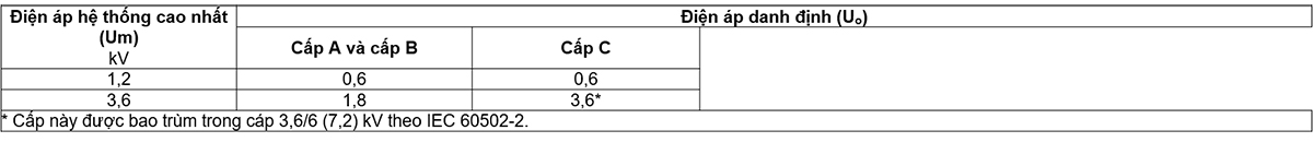
The rated voltages Uo/U(Um) of the cables considered in this standard are 0.6/1 (1.2) kV and 1.8/3 (3.6) kV.
NOTE 1 The above voltages are the correct symbols although in some countries other symbols are used, e.g. 1.7/3 kV or 1.9/3.3 kV instead of 1.8/ 3 kV.
In the voltage notation of Uo/U(Um) cables:
Uo is the rated power-frequency voltage between the conductor and earth or metallic screen for which the cable is designed;
U is the rated power-frequency voltage between conductors for which the cable is designed;
Um is the highest value of the “highest system voltage” that the equipment is allowed to use (see IEC 60038).
The rated voltage of the cable for a given application shall be suitable for the operating conditions in the system in which the cable is used. For the convenience of cable selection, the system is divided into the following three levels:
– Class A: This class includes systems in which the phase conductor, upon earthing or earthing, is disconnected from the system within 1 min;
– Class B: this class includes systems that in fault conditions still work during the time with an earth fault phase. According to IEC 60183, this time should not exceed 1 h. For cables covered by this standard, longer periods of time, but not exceeding 8 h in any case, may be accepted. Total time of occurrence of earth fault in any year should not exceed 125h;
– Class C: this class includes all systems that are not in class A or B.
NOTE 2 It is known that in a system where the earth fault is not isolated automatically and rapidly, abnormal stresses on the cable insulation during the earth fault will reduce the life of the cable. to a certain extent. If the system is expected to operate fairly frequently with prolonged earth faults, the system should be classified in class C.
Recommended Uo values for cables used in three-phase systems are listed in Table 1.
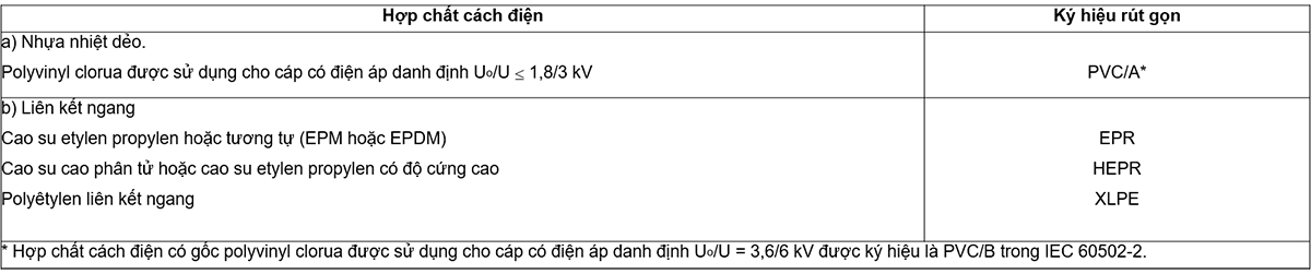
4.2. Insulating compound
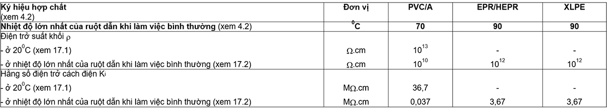
The classes of insulating compounds covered by this standard are listed in Table 2 together with abbreviated designations.
The highest conductor temperatures for the different classes of insulating compounds covered by this standard are given in Table 3.
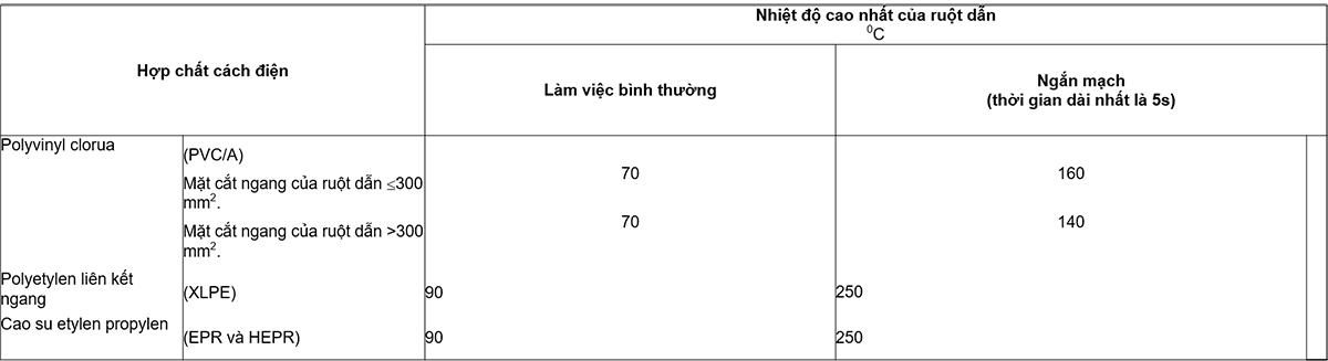
The temperatures in Table 3 are based on the inherent properties of the insulating material. It is important to take other factors into account when using these values to calculate the current rating.
For example, under normal operating conditions, if a cable directly buried in the ground is operated with a continuous load (100% load factor) at the highest conductor temperature indicated in the table, then Over time, the thermal resistance of the soil around the cable may increase from its original value due to the drying process of the soil. As a result, the conductor temperature can greatly exceed the highest value. If it is foreseen that such working conditions will be, then adequate provision should be made.
Refer to IEC 60724 for guidance on short circuit temperatures.
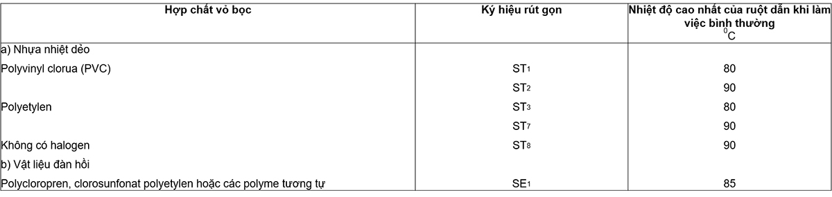
The highest conductor temperatures for the different types of sheathing compounds covered by this standard are given in Table 4.
5. Conductor
Conductors shall be class 1 or class 2 of uncoated or coated annealed copper or of aluminum or aluminum alloy or class 5 of uncoated or coated copper in accordance with IEC 60228.
6.1. Material
The insulation shall be an extruded dielectric of one of the two classes listed in Table 2.
For halogen-free cables, the insulation shall comply with the requirements given in Table 23.
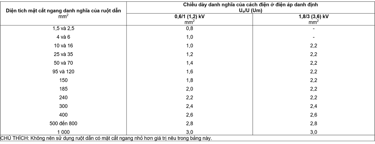
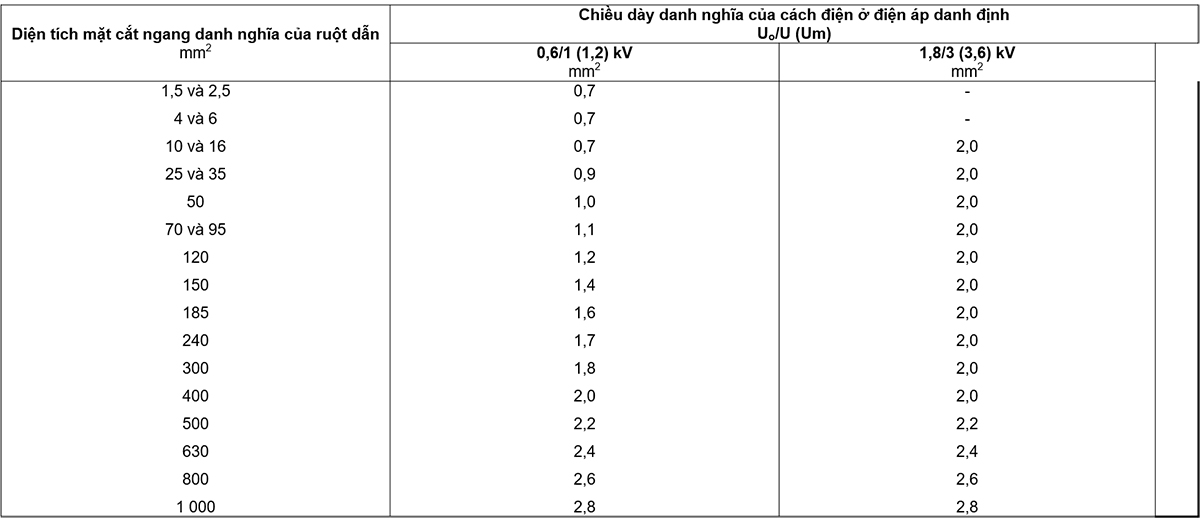
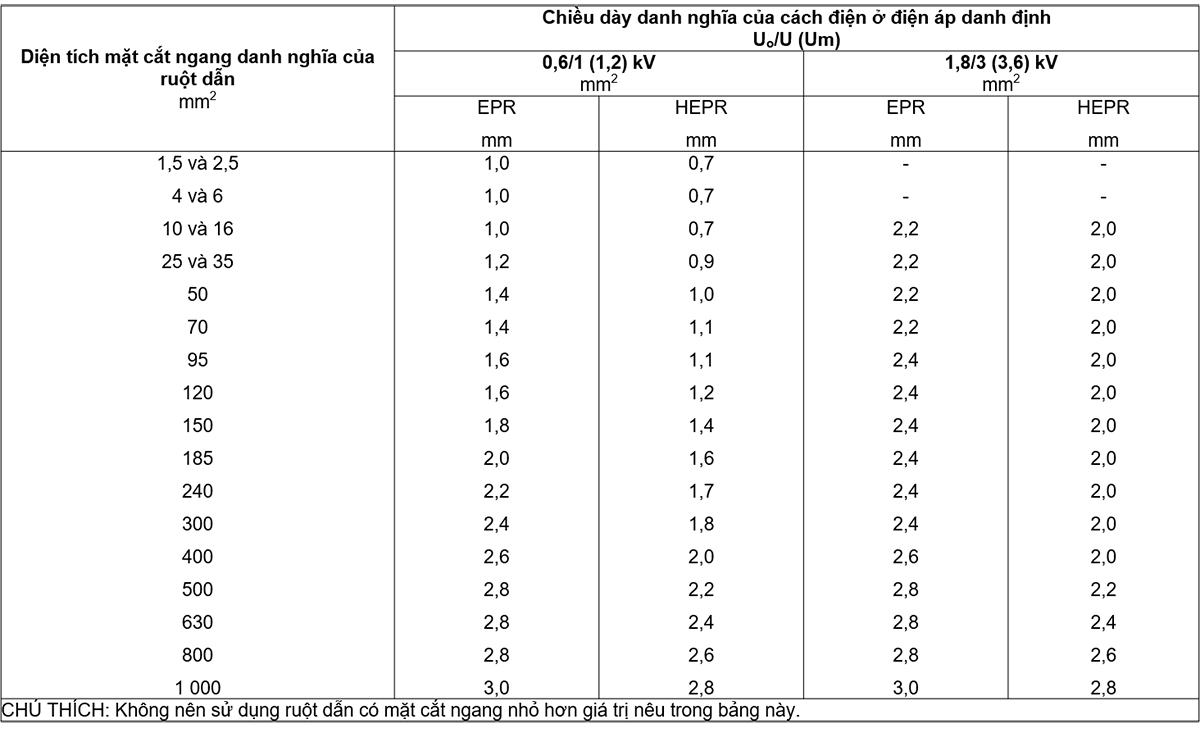
6.2. Insulation thickness
The nominal insulation thicknesses are specified in the tables from Tables 5 to 7.
The thickness of any insulation is not included in the insulation thickness.
7. Multi-core cable assembly, inner sheath and filler
The multi-core cable assembly depends on the rated voltage and whether a metal screen is applied to each core.
Subclauses 7.1 to 7.3 do not apply to sheathed single-core cable assemblies.
7.1.1. Structure
The inner wrap can be extruded or wound.
For cables with round cores, except cables with more than five cores, a wound inner covering is allowed only if the space between the cores is substantially filled.
Allows the use of a suitable bundle layer prior to extrusion of the inner wrap.
7.1.2. Material
The material used for the inner covering and filler shall be suitable for the operating temperature of the cable and compatible with the insulating material.
For halogen-free cables, the inner sheath and filler shall meet the requirements given in Table 23.
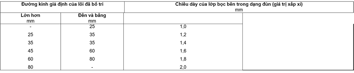
7.1.3. Thickness of extruded inner coating
The approximate thickness of the extruded inner coating shall be obtained from Table 8.
7.1.4. Thickness of the wrapped inner layer
The approximate thickness of the wound inner covering shall be 0.4 mm for the assumed diameter of the arranged core up to and including 40 mm and 0.6 mm for larger diameters.
7.2. Cable with rated voltage 0.6/1 (1.2) kV
Cables with a rated voltage of 0.6/1 (1.2) kV may have a common metallic layer around the cores.
NOTE The choice between cables with and without metallic coating depends on national regulations and installation requirements to prevent possible danger from mechanical damage or direct electrical contact.
7.2.1. Cables with a common metallic layer (see Clause 8)
The cable shall have an inner sheath surrounding the arranged core. Inner coatings and fillers shall be in accordance with 7.1.
However, metal cuffs may be applied directly to the assembled core, with the inner covering removed, provided that the nominal thickness of each cuff does not exceed 0.3 mm and that the complete cable is suitable. with the special bending test specified in 18.17.
7.2.2. Cables without a common metallic layer (see Clause 8)
The inner covering may be omitted provided that the outer shape of the cable remains essentially round and there is no adhesion between the cores and the sheath.
The sheath may penetrate the gaps between the cores, except in the case of a thermoplastic sheath over a circular core larger than 10 mm2.
However, if an inner coating is present, its thickness need not comply with 7.1.3 or 7.1.4.
7.3. Cable with rated voltage 1.8/3 (3.6) kV
Cables with rated voltage 1.8/3 (3.6) kV shall have a metallic layer surrounding individual or common cores.
7.3.1. Cables with only common metallic layer (see Clause 8)
The cable shall have an inner sheath surrounding the arranged core. Inner coatings and fillers shall be in accordance with 7.1 and shall not be hygroscopic.
7.3.2. Cables with a metallic layer surrounding each individual core (see Clause 9)
The metal layers of each individual core must be in contact with each other.
Cables with an additional common metal layer (see Clause 8) of material identical to that of the individual metal layers below shall have an internal sheath surrounding the arranged cores. Inner coatings and fillers shall be in accordance with 7.1 and shall not be hygroscopic.
When the individual underlying metal layers and the additional common metal are of different materials, they shall be separated by an extruded sheath of one of the materials specified in 13.2. For lead-sheathed cables, this separation may be made by means of an inner sheath according to 7.1.
For cables that are unarmoured, have no temporary copper conductors or have no common metallic layer (see Clause 8) the inner covering may be removed, provided that the external shape of the cable remains essentially the same. circle. The sheath may penetrate the gaps between the cores, except in the case of a thermoplastic sheath over a circular core larger than 10mm2. However, if an inner sheath is present, its thickness need not comply with 7.1.3 or 7.1.4
8. Metallic layer of single-core and multi-core cables
The following types of metallic grades are covered in this standard:
a) metal screens (see Clause 9);
b) concentric conductors (see Clause 10);
c) lead sheath (see Clause 11);
d) metal armor (see Clause 12).
The metallic layer(s) shall consist of one or more of the types listed above and shall be non-magnetic when applied to single-core cables or to individual cores of multi-core cables.
9.1. Structure
The metal screen shall be one or more ribbons, or a woven mesh or a layer of concentric wire, or a combination of wires and ribbon(s).
The metal screen may also be an enclosure or armor in the case of a general screen in accordance with 9.2.
When selecting screen materials, special consideration must be given to corrosion resistance, not only for mechanical safety but also for electrical safety.
The clearance in the screen shall be in accordance with national regulations and/or national standards.
9.2. Request
The dimensional, physical and electrical requirements of metal screens shall be defined in national regulations and/or national standards.
10.1. Structure
Clearances in centered conductors shall comply with national regulations and/or national standards.
When selecting concentric conductor materials, special consideration must be given to corrosion resistance, not only for mechanical safety but also for electrical safety.
10.2. Request
Dimensional and physical requirements of concentric conductors and concentric conductor resistance shall be defined in national regulations and/or national standards.
10.3. Set concentric conductor
When concentric conductors are required, this conductor shall be superimposed on the inner sheath in the case of multi-core cables; in the case of single-core cables, the concentric conductors shall be applied directly on the insulation or over the appropriate inner covering.
11.2. Lead sheath
The sheath shall be of lead or lead alloy and shall be laid as a reasonably tight-fitting seamless tube.
The nominal thickness shall be calculated according to the following formula:
tpb = 0.03 Dg + 0.7
Inside
tpb is the nominal thickness of the lead sheath, in millimetres;
Dg is the assumed diameter under the lead sheath, in millimeters (rounded to the first decimal in accordance with Annex B).
In all cases, the minimum nominal thickness shall be 1,2 mm. Calculated values shall be rounded to the first decimal place (see Annex B).
11.2. Other metal covers
Is considering.
The types of armor covered by this standard are as follows:
a) flat wire armor;
b) armor of round wire;
c) double tape armor.
NOTE For cables of rated voltage 0.6/1 (1,2) kV with a cross-sectional area exceeding 6 mm2, armor can be provided in the form of a woven galvanized steel wire mesh according to the agreement. agreement between manufacturer and purchaser.
Round wire or flat wire shall be galvanized steel, copper or tin coated copper, aluminum or aluminum alloy.
The ribbon must be steel, galvanized steel, aluminum or aluminum alloy. Steel strip shall be hot-rolled or cold-rolled of commercial quality.
In cases where a suitable steel armor wire layer with minimum conductivity is required, it is permissible to add sufficient quantities of tinned copper or copper wires in the armor layer to ensure compliance.
When selecting armor materials, special consideration must be given to corrosion resistance, not only for mechanical safety but also for electrical safety, especially when armor is used as a screen.
Armor of single-core cables for use in AC systems shall be of non-magnetic material, unless specially constructed armor is selected.
12.3.1. Single-core cable
In the case of single-core cables, an extruded or wound inner covering, of the thickness specified in 7.1.3 or 7.1.4, shall be placed under the armor.
12.3.2. Multi-core cable
In the case of multi-core cables, armor shall be applied over the inner sheath according to 7.1 except for special applications where metallic tape is used, see 7.2.1.
12.3.3. Separator sheath
Where the underlying metal and armor are made of different materials, they shall be separated by an extruded sheath made of one of the materials specified in 13.2.
For halogen-free cables, the separation sheath (ST8) shall meet the requirements given in Table 23.
When armor is required for lead-sheathed cables, the armor may be placed on top of a wound lining according to 12.3.4.
If separation sheath is used, it should be placed under the armor in place of the inner sheath or in addition to the inner sheath.
The nominal thickness of the separation sheath Ts, in millimeters, shall be calculated from the following formula:
Ts = 0.02 Du + 0.6
where Du is the assumed diameter under this sheath, in millimeters, calculated as described in Annex A.
The value calculated from this formula shall be rounded to the nearest 0.1 mm (see Annex B).
For cables without lead sheath, the nominal thickness shall not be less than 1,2 mm. For cables in which the separating sheath is placed directly over the lead sheath, the nominal thickness shall not be less than 1,0 mm.
12.3.4. Underarm wrap wraps for lead-sheathed cables
Wrap liner applied to a compound lead sheath by means of impregnated cuffs and in the form of a compound or a combination of two layers of impregnated paper tape and in the compound form followed by one or more of the compound materials. yarns.
Impregnation of the lining material can be done with bituminous compounds or other preservative compounds. In the case of wire armor, these compounds should not be placed directly under the armor.
Synthetic bandages may be used instead of impregnated paper tapes.
The total thickness of the wrap lining between the lead sheath and the armor after armor placement shall be approximately 1.5 mm.
12.4. The size of the armor wire and the armor ribbon
The nominal size of the armor wire and the best armor band is one of the values below:
Round rope:
Diameter 0.8 – 1.25 – 1.6 – 2.0 – 2.5 – 3.15 mm;
Flat wire:
Thickness 0.8 mm;
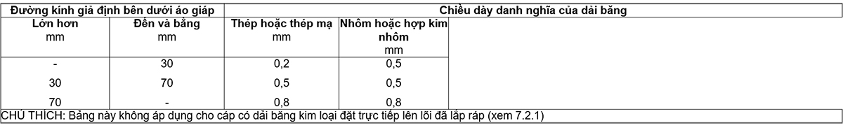
Steel ribbon:
Thickness 0.2 – 0.5 – 0.8 mm;
Aluminum or aluminum alloy ribbon:
Thickness 0.5 – 0.8 mm;
12.5. Relationship between cable diameter and armor size
The nominal diameter of the armor round wire and the nominal thickness of the armor band shall not be less than the values given in Tables 9 and 10 respectively.
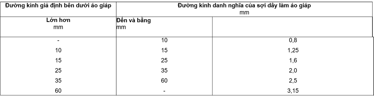
For flat wire armor and the assumed diameter under the armor is more than 15 mm, the nominal thickness of the flat wire shall be 0.8 mm. Cables of assumed diameter under armor up to and including 15 mm shall not be armored with flat wire.
12.6. Armor of round or flat wire
Wire armor must be closed, that is, leaves have the smallest gap between adjacent wires. Galvanized steel cuffs with a minimum nominal thickness of 0.3 mm may be used spirally wound over the armor with flat wire and over the armor with round wire, if necessary. The tolerances of the steel band shall be in accordance with 16.7.3.
When tape armor and an inner covering as specified in 7.1 are used, the inner covering shall be reinforced with a tape liner. The total thickness of the inner covering and the additional tape liner shall be as specified in 7.1 plus 0,5 mm if the thickness of the armor band is 0.2 mm and plus 0.8 mm if the thickness of the armor band is more than 0.2 mm.
The combined thickness of the inner wrap and the additional tape-type lining shall not be less than 0.2 mm of these values with a +20% posterior capacity.
If separation sheath is required or if the inner covering is extruded and meets the requirements of 12.3.3, no additional ribbon-type lining is required.
Bandage armor shall be spirally wound in two layers so that the outer band is approximately centered over the gap in the inner band. The clearance between adjacent loops of each ribbon shall not exceed 50% of the width of the ribbon.
13.1. General requirements
All cables must be sheathed.
The sheath is normally black, but other colors may be used by agreement between manufacturer and purchaser, but this color shall be appropriate to the particular conditions in which the cable is to be used.
NOTE The UV stability test is under consideration.
13.2. Material
The sheath shall be a thermoplastic compound (PVC or polyethylene or halogen-free) or elastomer compound (polychloroproprene, polyethylene chlorosulphonate or similar polymer).
Halogen-free sheath materials shall be used for cables with low flame spread characteristics, low smoke emissions and no halogen emissions when burned. The sheath (ST8) of halogen-free cables shall meet the requirements given in Table 23.
The enclosure material shall be suitable for operation with the temperatures according to Table 4.
Chemical additives to the sheath may be needed for special purposes, for example termite protection, but should not contain materials harmful to people and/or the environment.
NOTE Examples of materials9 considered unsuitable include:
Aldrin: 1,2,3,4,10, 10-hexachloro-1 ,4,4a,5,8,8a-hexahydro-1,4,5, 8-dimethanonaphthalene
Dieldrin: 1,2,3,4,10, 10-hexachloro-6 , 7-epoxy- 1,4,4a,5,6,7,8,8a-octahydro-1,4,5, 8-dimethanonaphthalene
Lindane: Gamma Isomer of 1,2,3,4,5, 6-hexachloro-cyclohexane .
13.3. Thickness
Unless otherwise specified, the nominal thickness ts, in millimetres, shall be calculated from the following formula:
Ts = 0.035 D + 1.0
where D is the assumed diameter immediately below the sheath, in millimetres (see Annex A).
The value obtained from this formula shall be rounded to the nearest 0,1 mm (see Annex B).
The nominal thickness shall not be less than 1.4 mm for single-core cables and 1.8 mm for multi-core cables.
14.1. Ambient temperature
Unless otherwise specified in the detailed description for a particular test, the tests shall be carried out at an ambient temperature of (20±15)0C.
14.2. Frequency and waveform of power frequency test voltages
The frequency of the a.c. test voltage shall be in the range 49 Hz to 61 Hz. The waveform is basically a sine wave. The values quoted are effective values.
14.3. Waveform of impulse test voltage
According to IEC 60230, the impulse wave shall have a real front time between 1 ms and 5 ms and a nominal time to half-peak between 40 ms and 60 ms. In other respects it shall be in accordance with IEC 60060-1.
15.1. General requirements
Routine tests are made on each manufactured cable segment (see 3.2.1). However, the number of cable segments to be tested can be reduced according to agreed quality control procedures.
Routine tests required in this standard are:
a) measure the conductor resistance (see 15.2);
b) voltage test (see 15.3).
15.2. Conductor resistance
Resistance measurements shall be made on all conductors of each cable segment submitted for routine testing, including concentric conductors, if any.
The complete cable segment, or a sample from it, shall be placed in a test room maintained at a reasonably constant temperature, for at least 12 h prior to the test. In case of doubt as to whether the conductor temperature is the same as room temperature, the resistance shall be measured after the cable has been placed in the test room for 24 h. Alternatively, the resistance can be measured on a sample of conductor conditioned for at least 1 h in a temperature controlled liquid bath.
The measured resistance value must be corrected to 200C temperature and 1 km length according to the formula and coefficients given in IEC 60228.
The d.c. resistance of each conductor at 200C shall not exceed the appropriate maximum value specified in IEC 60228. For concentric conductors, the resistance shall comply with national regulations and/or national standards. .
15.3. Voltage test
15.3.1. General requirements
The voltage test shall be made at ambient temperature, using a.c. voltage at power frequency or d.c. at the option of the manufacturer.
15.3.2. Test procedure for single-core cables
For single-core cables, the test voltage shall be applied for 5 min between the conductor and the metal screen.
Unscreened single-core cables shall be immersed in water at room temperature for 1 h and then apply a test voltage for 5 min between the conductor and the water.
NOTE The spark discharge test is under consideration for single-core cables without any metallic layers.
15.3.3. Test procedure for multicore cable
For multicore cables with individually screened cores, the test voltage shall be applied for 5 min between each conductor and the metal layer.
For multi-core cables without separate screens, the test voltage shall be applied for 5 min in turn between each insulated conductor and all remaining conductors and common metallic layers, if any.
Conductors may be suitably connected for successive application of test voltages to limit the total test time provided that the connection sequence ensures that the voltage is applied for a minimum of 5 min without there shall be no discontinuity between each conductor and each other and between each conductor and metallic layers, if any.
Alternatively, three-core cables can be tested in one operation using a three-phase transformer.
15.3.4. Test voltage
The power frequency test voltage shall be 2.5 Uo + 2 kV. The value of single-phase test voltage for standard rated voltage is given in Table 11.

For three-core cables, if the voltage test is made with a three-phase transformer, the test voltage between phases shall be 1,73 times the value given in the table above.
When d.c. voltage is used, the applied voltage shall be 2.4 times the power frequency test voltage.
In all cases, the test voltage shall be gradually increased to the specified value.
15.3.5. Request
Insulation breakdown shall not occur.
16.1. General requirements
Sample tests required in this standard are as follows:
a) check the conductors (see 16.4);
b) check the dimensions (see points 16.5 to 16.8);
c) Heat-furnace stretching test for EPR, HEPR and XLPE insulation and elastomeric sheath (see 16.9).
16.2. Sample testing frequency
16.2.1. Conductor check and size check
Conductor inspection, insulation and sheath thickness measurements and outside diameter measurements shall be made on a length of cable from each series of manufacture of the same type and of the same nominal cable cross-section, but shall be limited to no more than 10% of the cable segments in any contract.
16.2.2. Physical test
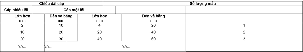
Physical tests shall be performed on samples taken from fabricated cables according to an agreed quality control procedure. In the absence of this agreement, for contracts where the total length exceeds 2 km for multi-core cables or 4 km for single-core cables, the test shall be carried out according to Table 12.
16.3. Repeat the test
If any one sample fails to pass any of the tests in Clause 16, two more samples shall be taken from the same lot and subjected to the same or more tests in which the original sample fails. If both additional samples pass the test, all cables in the lot from which the samples were taken are considered to comply with the requirements of this standard. If either of the two additional samples fails, the lot from which the samples were taken is considered nonconforming.
16.4. Conductor test
Compliance with the requirements for conductor construction in IEC 60228 is checked by inspection by measurement, where possible.
16.5. Measurement of insulation thickness and non-metallic sheath (including extruded separator sheath, but excluding extruded inner sheath)
16.5.1. General requirements
The test method shall be according to Clause 8 of IEC 60811-1-1.
Each length of cable selected for the test shall be represented by a length of cable taken from one end of the cable after removal of any possible damage, if necessary.
For cables with more than three cores having conductors of equal nominal cross-section, the number of cores on which the measurement is made shall be limited to three cores or 10% of the cores, whichever is greater.
16.5.2. Requirements for insulation
For each core segment, the average of the measured values, rounded to the nearest 0,1 mm in accordance with Annex B, shall not be less than the nominal thickness and such minimum value shall not be less than 90% of the value. nominally more than 0.1 mm, ie:
tm 0.9 tons – 0.1
Inside:
tm is the minimum thickness, in millimetres;
tn is the nominal thickness, in millimeters.
16.5.3. Requirements for non-metallic enclosures
The minimum thickness of the non-metallic sheath shall not be less than 80% of the nominal value by more than 0,2 mm, i.e.:
tm 0.8 ton – 0.2
16.6. Measure the thickness of the lead sheath
The minimum thickness of the lead sheath shall be determined by one of the following methods at the option of the manufacturer and shall not be less than 95% of the nominal thickness by more than 0,1 mm, i.e.:
tm 0.95 ton – 0.1
16.6.1. Ribbon method
Measurements shall be made with a micrometer having planes with diameters from 4 mm to 8 mm and with an accuracy of ±0.01 mm.
Measurements shall be made on a piece of test sheath approximately 50 mm long removed from the complete cable. The test piece shall be slit lengthwise and carefully flattened. After cleaning the test piece, make a sufficient number of measurements along the circumference of the enclosure and at least 10 mm from the edge of the flattened test piece to ensure that the minimum thickness is measured.
16.6.2. Ring method
Measurements shall be made with a micrometer having one flat and one spherical tip, or one flat and one flat rectangular tip of 0.8 mm wide and 2.4 mm long. The flat rectangular or spherical probe shall be placed on the inner surface of the rim. The accuracy of the micrometer shall be ±0.01 mm.
Measurements shall be made on a circular rim of the sheath carefully cut from the sample. The thickness shall be determined at a sufficient number of points along the circumference of the rim to ensure that the minimum thickness is measured.
16.7. Measure the armor wire and the armor band
16.7.1. Measure the rope
The diameter of the round wire and the thickness of the flat wire shall be measured in a flat-ended micrometer with an accuracy of ±0.01 mm. For round rope, two measurements are made at the same position in the direction perpendicular to each other and the diameter is taken as the average of these two values.
16.7.2. Measure the ribbon
Measurements shall be made with a micrometer having two flat probes approximately 5 mm in diameter with an accuracy of ±0.01 mm. For ribbons up to 40 mm wide, the thickness is measured at the center of the width. For wider ribbons, thickness is measured 20 mm from each edge of the tape and the thickness is taken as the average of the results.
16.7.3. Request
The dimensions of armor ropes and bands shall not be less than the nominal values given in 12.5 by more than:
– 5% for round rope;
– 8% for flat wire;
– 10% for ribbons.
16.8. Measure outside diameter
If the measurement of the outside diameter of the cable is required as a sample test, this measurement shall be made in accordance with Clause 8 of IEC 60811-1-1.
16.9. Heat-furnace stretching test for EPR, HEPR and XLPE insulation and elastomeric sheaths
16.9.1. Rule
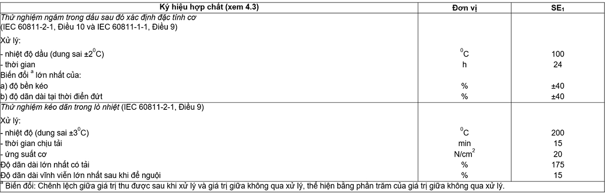
Sampling and testing procedures shall be carried out in accordance with Clause 9 of IEC 60811-2-1 using the conditions given in Tables 17 and 22.
16.9.2. Request
The test results shall conform to the requirements given in Table 17 for EPR, HEPR and XLPE insulation and Table 22 for SE1 enclosures.
Samples of complete cables between 10 m and 15 m in length are subjected to the following tests, applied in turn:
a) measure insulation resistance at ambient temperature (see 17.1);
b) insulation resistance measurement at maximum conductor temperature in normal operation (see 17.2);
c) voltage test for 4 h (see 17.3).
Cables with a rated voltage of 1,8/3 (3,6) kV are also subjected to the impulse test on each complete sample of cable, having a length of 10 m to 15 m (see 17.4).
Tests are limited to no more than three cores.
17.1. Measure insulation resistance at ambient temperature
17.1.1. Process
This test shall be made on the sample segment before any other electrical test.
All oversheaths shall be removed and the core immersed in water at ambient temperature for at least 1 h prior to the test.
Apply the d.c. test voltage from 80V to 500 V for a time sufficient to reach a reasonably stable measurement value, but not less than 1 min and not more than 5 min.
Measurements shall be made between each conductor and the water.
If required, the measurement can be confirmed at a temperature of (20±1)°C.
17.1.2. Calculate
The mass resistivity shall be calculated from the measured insulation resistance according to the following formula:

Inside
 is the mass resistivity, in ohm-centimeter;
R is the measured insulation resistance, in ohms;
I is the cable length, in centimeters;
D is the outside diameter of the insulation, in millimetres;
d is the inside diameter of the insulation, in millimetres;
The “insulation resistance constant Ki” expressed in megohm-km can also be calculated by the formula:

NOTE For profiled conductor cores, the ratio D/d is the ratio between the outer circumference of the insulation and the outer circumference of the conductor.
17.1.3. Request
The value calculated from the measurements shall not be less than the values specified in Table 13.
17.2. Measurement of insulation resistance at maximum conductor temperature
17.2.1. Process
The core of the cable sample shall be immersed in water at the maximum conductor temperature in normal operation ±20 °C for at least 1 h prior to the test.
Apply the d.c. test voltage from 80 V to 500 V for a time sufficient to obtain a reasonably steady measurement value, but not less than 1 min and not more than 5 min.
Measurements shall be made between each conductor and the water.
17.2.2. Calculate
The mass resistivity and/or insulation resistance constant shall be calculated from the insulation resistance according to the formula given in 17.1.2.
17.2.3. Request
The value calculated from the measurements shall not be less than the value specified in Table 13.
17.3. Voltage test for 4h
17.3.1. Rule
The core of the cable sample shall be immersed in water at ambient temperature for at least 1 h.
Then a power frequency voltage of 4 Uo must be applied and maintained continuously for 4 h between each conductor and the water.
17.3.2. Request
Insulation breakdown shall not occur.
17.4. Impulse test for cables with a rated voltage of 1,8/3 (3,6) kV
17.4.1. Process
The test shall be made on the sample at a conductor temperature between 50 °C and 100 °C above the maximum conductor temperature in normal operation.
The impulse voltage is applied according to the procedure given in IEC 60230 and shall have a peak value of 40 kV.
For multicore cables in which the cores are not individually screened, each pulse train shall be applied in turn between each phase conductor and all the remaining conductors interconnected and to earth.
17.4.2. Request
Each cable core must withstand 10 positive voltage spikes and 10 negative voltage spikes without damage.
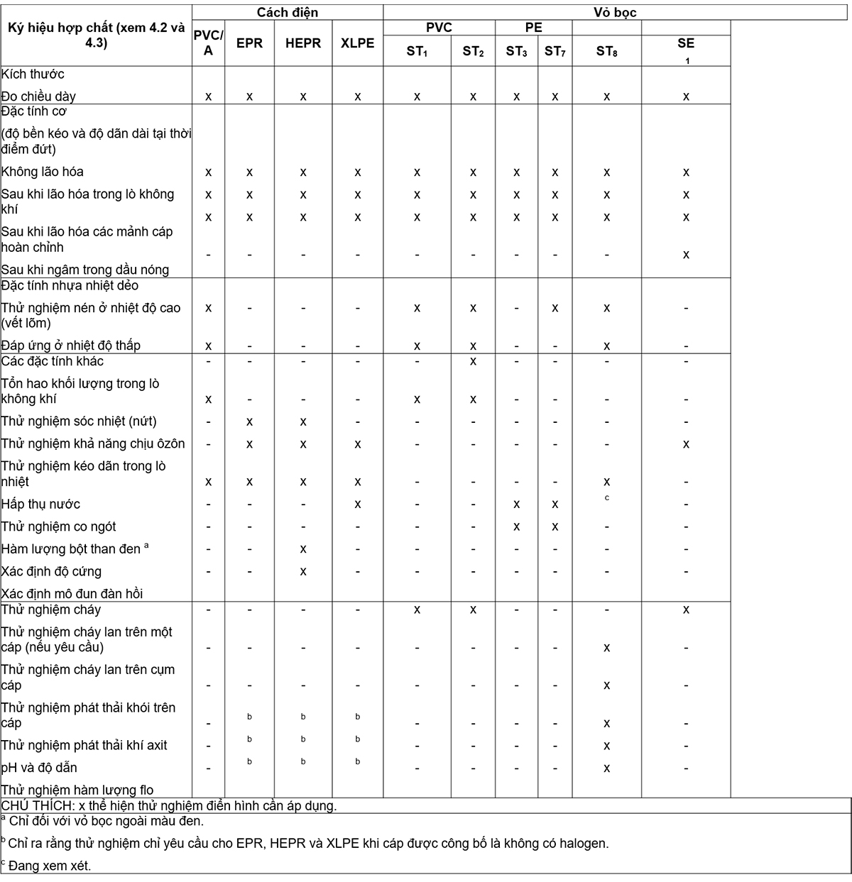
Non-electrical type tests required in this standard are given in Table 14.
18.1. Measure insulation thickness
18.1.1. Sample
One sample shall be taken from each insulated cable core.
For cables with more than three cores having conductors of equal nominal cross-section, the number of cores on which the measurement is made shall be limited to three cores or 10% of the cores, whichever is greater.
18.1.2. Process
The measurement shall be made as described in 8.1 of IEC 60811-1-1.
18.1.3. Request
See 16.5.2.
18.2. Thickness measurement of non-metallic sheath (including extruded separator sheath but excluding inner sheath)
18.2.1. Sample
A cable sample must be obtained.
18.2.2. Process
The measurement shall be made as described in 8.2 of IEC 60811-1-1.
18.2.3. Request
See 16.5.3.
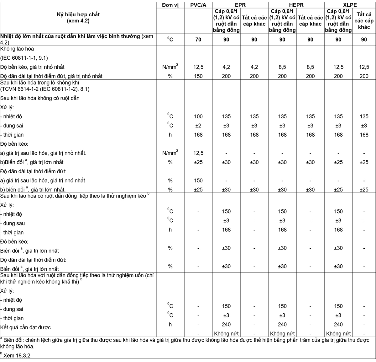
18.3. Test to determine the mechanical properties of insulation before and after aging
18.3.1. Sample
Sampling and test piece preparation shall be carried out as described in 9.1 of IEC 60811-1-1.
18.3.2. Treatment of aging
The aging treatment shall be carried out as described in 8.1 of IEC 60811-1-2 under the conditions specified in Table 15.
The tensile and flexural tests after aging with copper conductors of Table 15 are applicable to 0.6/1 (1.2) kV cables only. Only make the bend test on cables whose insulation cannot withstand the tensile test.
NOTE Tensile and flexural tests after aging are recommended in the presence of copper conductors. However, at the present time there is not enough information to enforce these requirements but only by agreement between the manufacturer and the purchaser.
18.3.3. Stabilization and mechanical testing
Stabilization and measurement of mechanical properties shall be carried out as described in 9.1 of IEC 60811-1-1.
18.3.4. Request
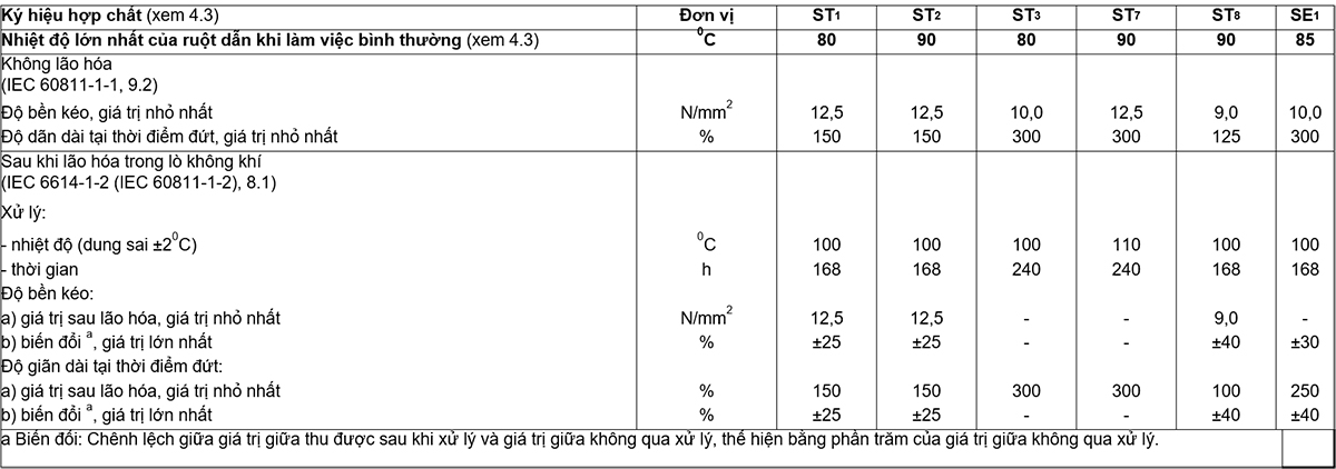
The test results for aged and unaged test pieces shall comply with the requirements given in Table 15.
18.4. Test to determine the mechanical properties of non-metallic sheaths before and after aging
18.4.1. Sample
Sampling and test piece preparation shall be carried out as described in 9.2 of IEC 60811-1-1.
18.4.2. Treatment of aging
The aging treatment shall be carried out as described in 8.1 of IEC 60811-1-2 under the conditions specified in Table 18.
18.4.3. Stabilization and mechanical testing
Stabilization and measurement of mechanical properties shall be carried out as described in 9.2 of IEC 60811-1-1.
18.4.4. Request
The test results for aged and unaged test pieces shall comply with the requirements given in Table 18.
18.5. Additional aging test on complete cable pieces
18.5.1. General requirements
The purpose of this test is to check that insulation and non-metallic sheathing are not degraded in service due to contact with other components in the cable.
The test applies to all cable types.
18.5.2. Sample
The sample shall be taken from the complete cable as described in 8.1.4 of IEC 60811-1-2.
18.5.3. Treatment of aging
Aging treatment of cable pieces shall be carried out in an air furnace as described in 8.1.4 of IEC 60811-1-2 under the following conditions:
– temperature: (10 ± 2)°C greater than the highest temperature of the conductors of the cable in normal operation (see Table 15);
– time: 7 x 24 h.
18.5.4. Mechanical test
The test piece, which is insulation and sheath taken from an aged cable piece, shall be prepared and subjected to the mechanical tests as described in 8.1.4 of IEC 60811-1-2.
18.5.5. Request
The difference between the intermediate values of tensile strength and elongation at break after aging and the corresponding values obtained without aging (see 18.3 and 18.4) shall not exceed the applicable values. for the post-aging test in an air furnace specified in Table 15 for insulation and Table 18 for non-metallic enclosures.
18.6. Weight loss test of class PVC sheath ST2
18.6.1. Process
Sampling and testing procedures shall be in accordance with 8.2 of IEC 60811-3-2.
18.6.2. Request
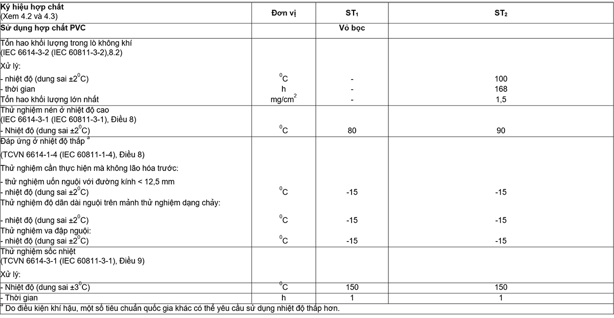
The test results shall conform to the requirements given in Table 19.
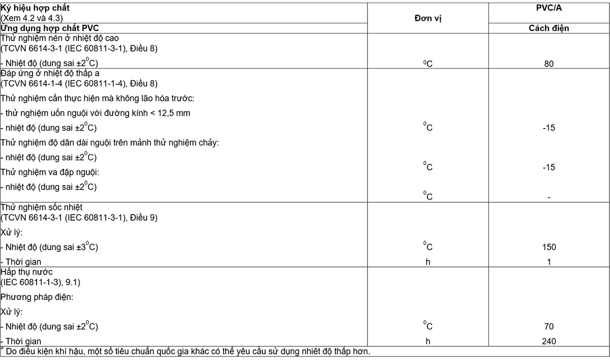
18.7. High-temperature compression test on non-metallic insulation and sheaths
18.7.1. Process
The high-temperature compression test shall be carried out in accordance with Clause 8 of IEC 60811-3-1, using the test conditions given in the test method and in Tables 16 and 20. .
18.7.2. Request
The test results shall conform to the requirements given in Clause 8 of IEC 60811-3-1.
18.8. Tested on PVC insulation and PVC sheath and halogen-free sheath at low temperature
18.8.1. Process
The sampling and test procedures shall be in accordance with Clause 8 of IEC 60811-1-4, using the test temperatures specified in Tables 16, 19 and 21.
18.8.2. Request
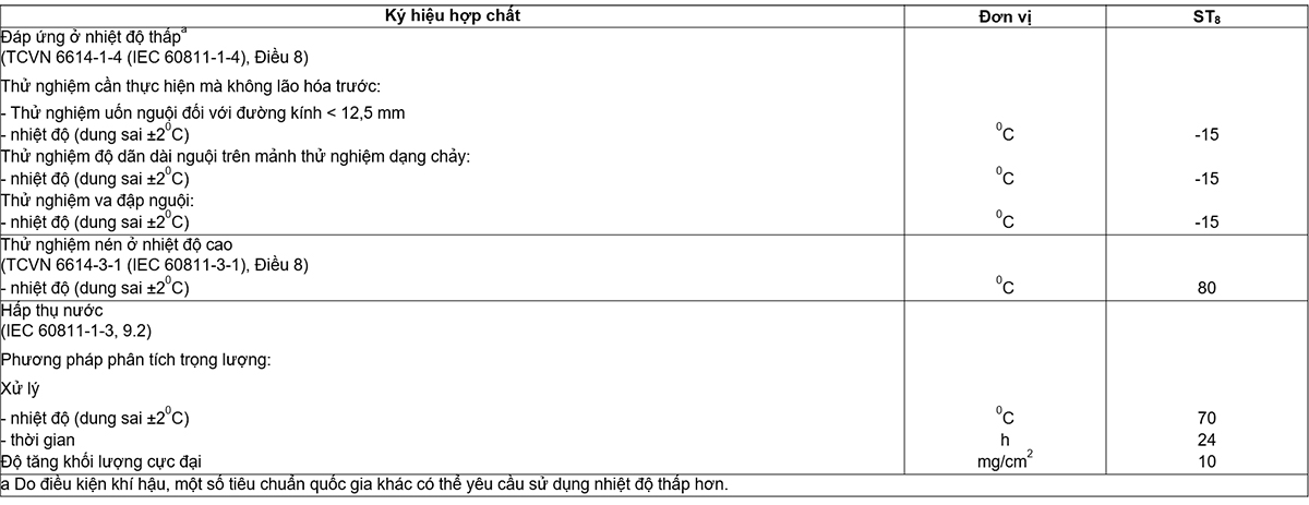
The test results shall conform to the requirements given in Clause 8 of IEC 60811-1-4.
18.9. Crack resistance test of PVC insulation and PVC sheath (thermal shock test)
18.9.1. Process
The sampling and testing procedure shall be in accordance with Clause 9 of IEC 60811-3-1, using the test temperatures and times according to Tables 16 and 19.
18.9.2. Request
The test results shall conform to the requirements given in Clause 9 of IEC 60811-3-1.
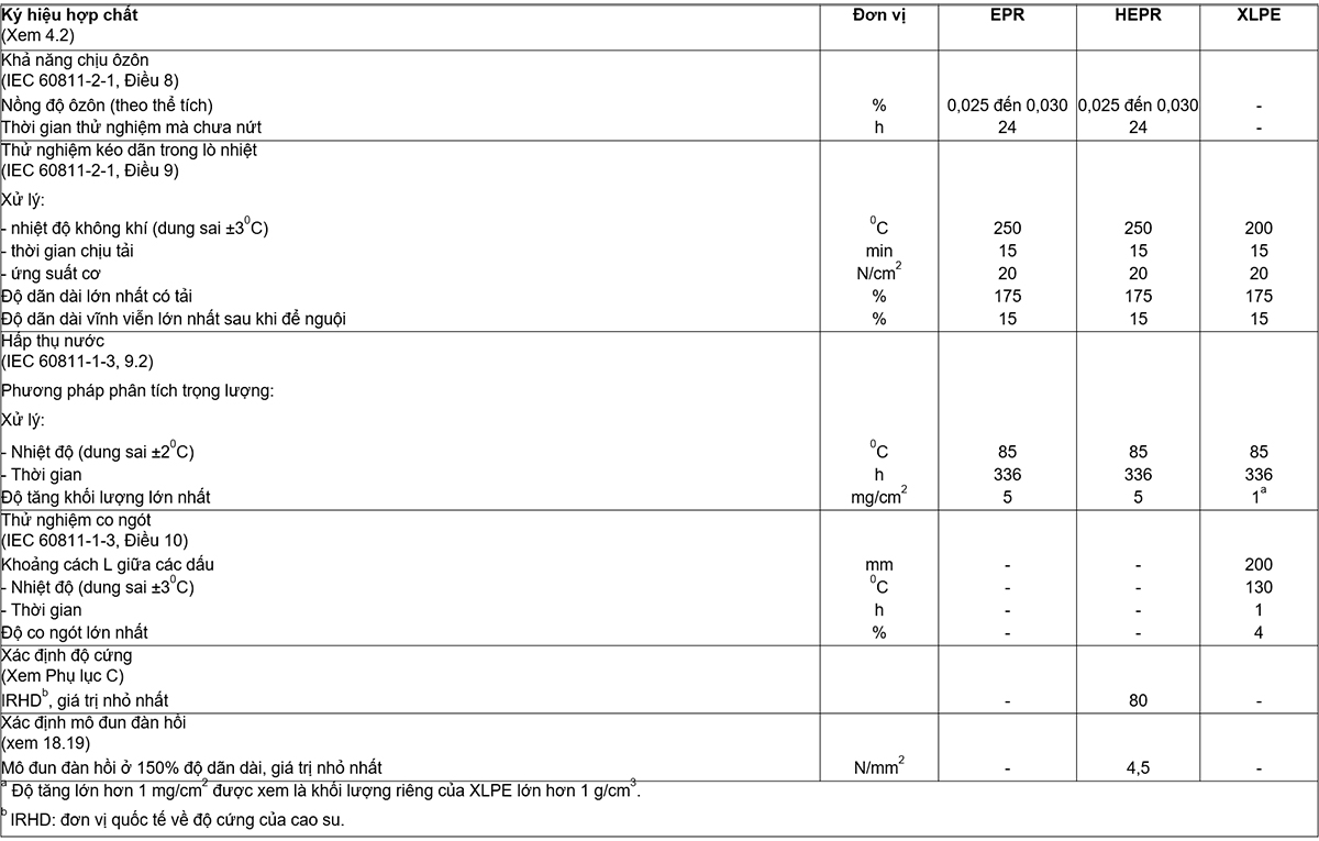
18.10. Ozone resistance test of EPR and HEPR . insulation
18.10.1. Process
Sampling and testing procedures shall be carried out in accordance with Clause 8 of IEC 60811-2-1. The ozone concentration and test duration shall be in accordance with Table 17.
18.10.2. Request
The test results shall conform to the requirements given in Clause 8 of IEC 60811-2-1.
18.11. Heat-furnace stretching test of EPR, HEPR and XLPE insulation and elastomer sheath
Sampling and testing procedures shall be carried out in accordance with 16.9 and shall conform to the requirements of 16.9.
18.12. Oil immersion test for elastomeric sheaths
18.12.1. Process
Sampling and testing procedures shall be carried out in accordance with Clause 10 of IEC 60811-2-1, using the conditions given in Table 22.
18.12.2. Request
The test results shall conform to the requirements given in Table 22.
18.13. Water absorption test of insulation
18.13.1. Process
Sampling and testing procedures shall be carried out in accordance with 9.1 or 9.2 of IEC 60811-1-3, using the conditions specified in Tables 16 or 17 respectively.
18.13.2. Request
The test results shall conform to the requirements specified in 9.1 of IEC 60811-1-3 or Table 17 respectively.
18.14.1. Fire spread test on a cable
This test is only made on cables sheathed with compound ST1, ST2 or SE1 where special requirements are required.
The test method and requirements are as specified in IEC 60332-1.
18.14.2. Fire spread test on cable assemblies
This test is performed on ST8 halogen-free sheathed cables.
The test method and requirements are as specified in IEC 60332-3-24.
18.14.3. Smoke emission test
This test is performed on ST8 halogen-free sheathed cables.
The test method and requirements are as specified in IEC 61034-2.
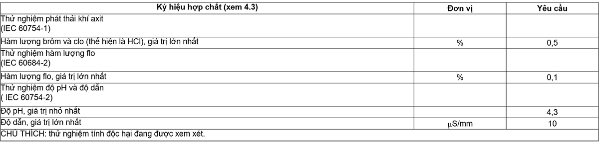
18.14.4. Acid gas emission test
This test shall be performed on the non-metallic components of the ST8 halogen-free sheathed cable.
18.14.4.1. Process
The test method is as specified in IEC 60754-1.
18.14.4.2. Request
The test results shall conform to the requirements in Table 23.
18.14.5. pH and conductivity test
This test shall be performed on the non-metallic components of the ST8 halogen-free sheathed cable.
18.14.5.1. Process
The test method is as specified in IEC 60754-2.
18.14.5.2. Request
The test results shall conform to the requirements in Table 23.
18.14.6. Test for fluorine content
This test shall be performed on the non-metallic components of the ST8 halogen-free sheathed cable.
18.14.6.1. Process
The test method is as specified in IEC 60684-2.
18.14.6.2. Request
The test results shall conform to the requirements in Table 23.
18.14.7. Toxicity test
Is considering.
NOTE The test method is being developed by the IEC.
18.15. Measure the carbon black powder content of the black PE sheath
18.15.1. Process
Sampling and testing procedures shall be carried out in accordance with Clause 11 of IEC 60811-4-1.
18.15.2. Request
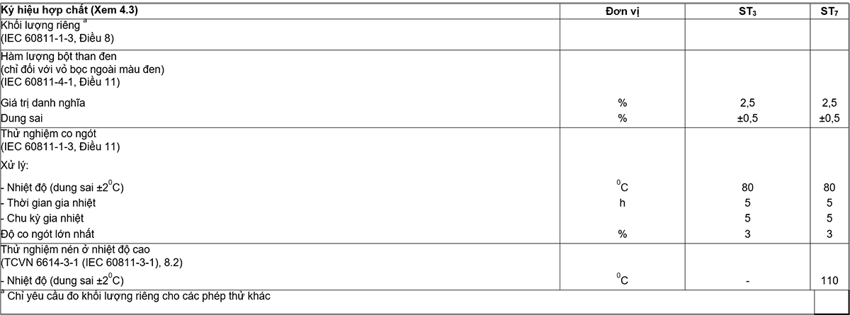
The test results shall conform to the requirements given in Table 20.
18.16. XLPE . insulation shrinkage test
18.16. Process
Sampling and testing procedures shall be carried out in accordance with Clause 10 of IEC 60811-1-3 under the conditions specified in Table 17.
18.16.2. Request
The test results shall conform to the requirements given in Table 17.
This test shall be carried out on multicore cables of rated voltage 0.6/1 (1,2) kV, having a common metal layer in the form of a metal strip placed directly over the assembled cores and removed. take the inner wrapper.
18.17.1. Process
The specimen shall be bent around a test cylinder (for example, the shaft of the drum) at ambient temperature with at least one complete turn. The diameter of the post shall be 7 D ± 5% where D is the actual outside diameter of the cable specimen. Then, unload the cable and repeat the process with the opposite bending direction.
This operation cycle must be performed three times. The specimen, which remains bent around the shaft, shall then be placed in an air furnace heated to the highest conductor temperature during normal cable operation for 24 h.
After the cable has cooled, and while the cable is still bent, the voltage test according to 15.3.
18.17.2. Request
No disruptive discharge shall occur and the enclosure shall show no signs of cracking.
18.18. Determination of the stiffness of HEPR . insulation
18.18.1. Process
Sampling and testing procedures shall be carried out in accordance with Annex C.
18.18.2. Request
The test results shall conform to the requirements given in Table 17.
18.19. Determination of elastic modulus of HEPR . insulation
18.19.1. Process
Sampling, test piece preparation and test procedures shall be carried out in accordance with Clause 9 of IEC 60811-1-1.
The required loads shall be measured to obtain 150% elongation. The corresponding stress is calculated by dividing the measured load by the cross-sectional area of the unstretched test piece. The stress-strain ratios shall be determined to obtain the elastic moduli at 150% elongation.
The modulus of elasticity shall be the middle value.
18.19.2. Request
The test results shall conform to the requirements given in Table 17.
18.20. Shrinkage test for PE . outer sheath
18.20.1. Process
Sampling and testing procedures shall be carried out in accordance with Clause 11 of IEC 60811-1-3 under the conditions specified in Table 20.
18.20.2. Request
The test results shall conform to the requirements given in Table 20.
NOTE For halogen-free enclosures, a test method is under consideration.
18.21. Additional mechanical testing on halogen-free housing
These tests are intended to verify that the halogen-free enclosure is not damaged during installation and operation.
NOTE Abrasion, tear and thermal shock tests are under consideration.
18.22. Water absorption test for halogen-free enclosure
18.22.1. Process
Sampling and testing procedures shall be carried out in accordance with 9.2 of IEC 60811-1-3 using the conditions specified in Table 21.
18.22.2. Request
The test results shall conform to the requirements of Table 21.
19. Electrical test after installation
When required, a post-installation test is performed when the installation of the cable and its accessories is complete.
A d.c. voltage of 4 Uo shall be applied for 15 min.
NOTE Electrical tests on repaired installations are subject to installation requirements. The above test is for new installations only.
APPENDIX A
(rule)
ASSUMPTIONAL CALCULATION METHODS TO DETERMINATE THE SIZE OF THE PROTECTION CLASS
The thickness of the cable sheaths, such as sheath and armor, is often related to the nominal cable diameter according to the “gradient”.
Sometimes this causes some problems. The nominal calculated diameters are not necessarily the same as the actual values achieved in production. In extreme cases, doubts may arise if the thickness of the coating does not correspond to the actual diameter, because the calculated diameters differ slightly. Differences in the size of profiled conductors between different manufactures and calculations give rise to differences in rated diameters and therefore may result in different coating thicknesses being used on the same Basic design of the cable.
To eliminate this problem, a hypothetical calculation method must be used. The essence of this method is to ignore the shape and degree of compaction between the conductors, and calculate only the assumed diameter using a formula based on the cross-sectional area of the conductor, the nominal thickness of insulation and number of cores. The thickness of the sheath and other coatings are then related to the assumed diameter through formulas or tables. The method of calculating the assumed diameter is precisely specified and there is no ambiguity as to the thickness of the coating that should be used as they are not subject to slight variations in actual manufacturing. This will standardize the cable design, the thickness of which is pre-calculated and specified for each conductor cross-section.
The assumed calculation method is only used to determine the dimensions of the sheaths and sheaths of the cables. This method cannot be used as a substitute for the calculation of the actual diameter required for practical purposes, which must be done separately.
A.1. General requirements
The hypothetical method below, for calculating different sheath thicknesses in a cable, has been adopted to ensure that any discrepancies that may arise in independent calculations are eliminated, for example as due to the assumption of conductor dimensions and the inevitable difference between the nominal and actual diameters achieved.
All thickness and diameter values shall be rounded to the first decimal according to the rules in Annex B.
Holding tape, e.g. anti-helical tape on armor, if not thicker than 0.3 mm, is omitted from this calculation method.
A.2. Method
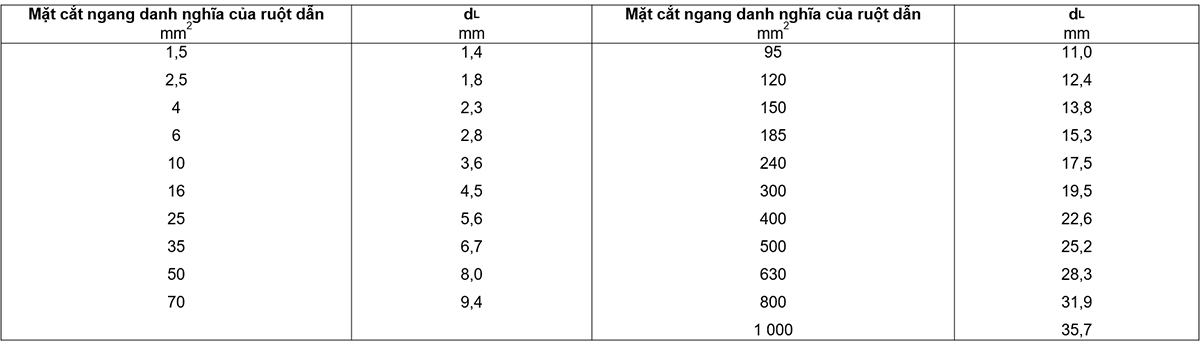
A2.1. Conductor
The assumed diameter (dL) of the conductor, excluding shape and tightness, for each of the nominal cross-sections given in Table A.1.
A.2.2. Core
The assumed diameter Dc of any core is determined as follows:
Dc = dL + 2ti
where ti is the nominal thickness of the insulation, in millimetres (see Tables 5 to 7).
If a metallic screen or concentric conductor is used, further additions shall be made in accordance with A.2.5.
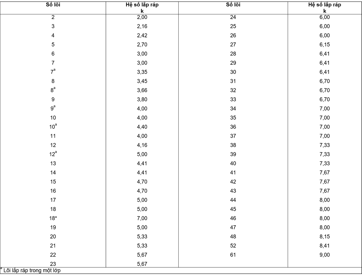
A.2.3. Diameter of arranged cores
The assumed diameter of the arranged cores (Df) is given by:
for cables with all conductors having the same nominal cross-sectional area:
Df = k Dc
where the assembly factor k is given in Table A.2.
for core-tank cables with one conductor of reduced cross-section:
Df = 
Inside
Dc1 is the assumed diameter of the insulated phase conductor, including the metallic layer, if any, in millimetres.
Dc2 is the assumed diameter of conductor with reduced cross-section, including insulation or cladding, if any, in millimetres.
A.2.4. Inner coating
The assumed diameter of the inner wrap (DB) is determined by:
DB = Df + 2tB
Inside:
tB = 0.4 mm for the assumed diameter of arranged cores (Df) up to and including 40 mm;
tB = 0.6 mm for Df greater than 40 mm.
The assumed values of tB apply to:
a) multi-core cable:
– whether or not there is an inner covering;
– whether the inner coating is extruded or wound;
Unless a separator conforming to 12.3.3 is used in place of the inner covering or in addition to the inner covering, A.2.7 shall apply.
b) single-core cable:
When an inner wrap is used regardless of extrusion or wrapping
A.2.5. Concentric conductors and metal screens
The increase in diameter due to concentric conductors or metallic screens is given in Table A.2.
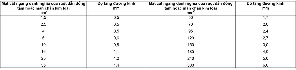
If the cross-section of a concentric conductor or metallic screen lies between the two values given in the table above, the increase in diameter is chosen for the value of the larger cross-section of the two.
If a metal screen is used, the cross-sectional area of the screen to be used in the table above shall be calculated in the following manner:
a) ribbon screens:
cross-sectional area = nt x tt x wt
Inside:
nt is the number of bands;
tt is the nominal thickness of an individual tape, in millimetres;
wt is the nominal width of an individual ribbon, in millimeters.
Where the total thickness of the screen is less than 0.15 mm, the increase in diameter shall be zero;
– for tape-wrap screens made of two tapes or one tape with overlapping sections, the total thickness being twice the thickness of one tape;
– for longitudinal tape-type screens.
· if the overlap is less than 30%, the total thickness is the thickness of the tape;
· if the overlap is greater than or equal to 30 %, the total thickness is twice the thickness of the tape.
b) rope screen (reverse spiral, if any)
cross-sectional area =

Inside
nw is the number of ropes;
dw is the diameter of a single wire, in millimetres;
h is the number of spirals in the opposite direction;
th is the thickness of a counter-helix, in millimetres, if more than 0.3 mm;
wh is the width of one helix in the opposite direction, in millimeters.
A.2.6. Lead sheath
The assumed diameter of the lead sheath (Dpb) is given by:
Dpb = Dg + 2tpb
Inside:
Dg is the assumed diameter under the lead sheath, in millimeters;
Tpb is the thickness according to Article 11, in millimeters;
A.2.7. Separator sheath
The assumed diameter of the separator sheath (Ds) is given by:
Ds = Du + 2ts
Inside
Du is the assumed diameter below the separator sheath, in millimetres;
ts is the thickness in millimeters according to 12.3.3.
A.2.8. Stacked wrap liners
The assumed diameter of the stacked wrap liner (Dlb) is given by:
Dlb = Dulb + 2tlb
Inside
Dulb is the assumed diameter below the stacked wrap lining, in millimeters;
tlb is the thickness of the stacked wrap liner, i.e. 1.5 mm according to 12.3.4.
A.2.9. Additional liners for cables with ribbon armor (wrap on inner sheath)

A.2.10. Armor
The assumed diameter of the armor (Dx) is determined:
a) for flat or round wire armor:
Dx = DA + 2tA + 2tw
Inside
DA is the diameter under the armor, in millimeters;
tA is the thickness or diameter of the armor wire, in millimetres;
tw is the thickness of the counter-helix, if any, in millimetres, if greater than 0.3 mm.
b) for double wound armor:
DX = DA + 4tA
Inside
DA is the diameter below the armor, in millimeters;
tA is the thickness of the armor tape, in millimeters.
(rule)
B.1. Rounding numbers for hypothetical calculation methods
The following rules apply when rounding numbers during the calculation of the hypothetical diameter and the determination of the dimensions of the component classes in accordance with Annex A.
At any step, when the calculated value has more than one decimal place, the value must be rounded to the nearest decimal place, i.e. to the nearest 0.1 mm. The assumed diameter at each step shall be rounded to the nearest 0.1 mm and when used to determine the thickness or dimensions of an outer layer, this diameter shall be rounded before being used in formulas or tables. suitable. The thickness is calculated from the assumed diameter value rounded which in turn is rounded to the nearest 0,1 mm as specified in Annex A.
To illustrate the above rules, give the following practical examples:
a) when the digit at the second decimal place before rounding is 0, 1, 2, 3 or 4, the digit at the first decimal place is unchanged (round down).
Eg:
2.12 @ 2.1
2.449 @ 2.4
25.0478 @ 25.0
b) when the digit in the second decimal place before rounding is 9,8,7,6 or 5, the digit in the first decimal place is incremented by one (rounded up).
Eg:
2.17 @ 2.2
2.453 @ 2.5
30,050 @ 30.1
B.2. Rounding numbers for other purposes
For purposes other than those mentioned in B.1, values rounded to more than one decimal place may be required. This can happen, for example, when calculating the average of several measurements or calculating the minimum using a percentage tolerance for a given nominal value. In these cases, rounding will be rounded to the decimal places specified in the respective clauses.
The method of rounding numbers is:
a) if after the last digit retained, before rounding, are the numbers 0, 1, 2, 3 or 4, then the last digit retained is preserved (rounded down)
b) if after the last digit retained, before rounding, are the numbers 9,8,7,6 or 5 then this last digit retained will be incremented by one (rounded up)
Eg:
2.449 @ 2.45 round to two decimal places
2.449 @ 2.4 rounded to one decimal
25.0478 @ 25,048 round to three decimal places
25.0478 @ 25.05 round to two decimal places
25.0478 @ 25.0 round to one decimal.
(rule)
DETERMINATION OF THE HARDWARE OF HEPR INSULATION
C.1. Test piece
The test piece shall be a complete sample of cable with all oversheath of the HEPR insulation to be measured carefully removed. Alternatively, an insulating core sample can be used.
C.2. Test procedure
Tests are carried out in accordance with ISO 48 with the exceptions indicated below.
C.2.1. The surface of the large work radius
The test device, in accordance with ISO 48, shall be constructed so that it can rest firmly on the HEPR insulation and allow the feet of the compression tool and the marker to come into vertical contact with this surface. This is done in one of two ways:
a) the tool is fitted with movable pins in universal joints so that they self-adjust on curved surfaces;
b) the base of the measuring instrument is fitted with two parallel bars A and A’ separated by a distance depending on the curvature of the surface (see Figure C.1).
The above methods can be used on surfaces with radius of curvature as small as 20 mm.
When the thickness of the HEPR insulation to be tested is less than 4 mm, a measuring instrument as described in the method in ISO 48 shall be used for thin and small test pieces.
C.2.2. Surface of small radius of curvature
On surfaces where the radius of curvature is too small for the procedures described in C.2.1, the test piece shall be supported on the same rigid base as the test tool in a manner that minimizes overall displacement the action of the HEPR insulation when the marking force is increased on the marking device and so that the marker is above the vertical axis of the test piece. Suitable procedures are as follows:
a) by placing the test piece in a groove or chute in a metal mold (see Figure C.2a);
b) by placing the conductor ends of the test piece in the V-block (see Figure C.2b).
The minimum radius of curvature of the surface to be measured according to the above methods shall be at least 4 mm.
For smaller radii, a measuring instrument as described in the method in ISO 48 shall be used for thin and small test pieces.
C.2.3. Stability and test temperature
The minimum time between production, i.e. vulcanization and testing should be 16 h.
The test shall be carried out at a temperature of (20 ± 2) °C and the test pieces shall be maintained at this temperature for at least 3 h immediately prior to the test.
C.2.4. Number of measurements
One measurement shall be made at each of the three or five different points distributed around the test piece. The middle value of the results is taken as the hardness of the test piece, recorded in the report to the nearest whole number in terms of international rubber hardness (IRHD).
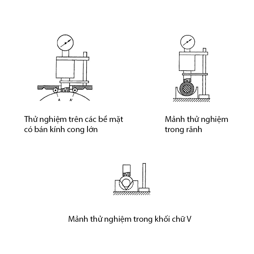
TABLE OF CONTENTS
Preface
1. Scope of application
2. References
3. Terms and definitions
4. Voltage symbols and materials
5. Conductor
6. Insulation
7. Multi-core cable assembly, inner sheath and filler
8. Metallic layer of single-core and multi-core cables
9. Metal curtain
10. Concentric conductor
11. Metal cover
12. Metal armor
13. Outer cover
14. Test conditions
15. Test it often
16. Sample test
17. Electrical type test
18. Non-electrical type test
19. Electrical test after installation
Annex A (specified) – Presumptive calculation method for determining the size of the protective covering
Appendix B (regulatory) – Rounding off
Annex C (normative) – Determination of stiffness of HEPR . insulation.