National standard TCVN 8090:2009 (IEC 62219 : 2002) on Bare wires for overhead power transmission lines – Bare wires with filaments twisted into concentric layers.
NATIONAL STANDARDS
TCVN 8090 : 2009
IEC 62219 : 2002
Ceiling WIRE FOR Aerial ELECTRICAL TRADE LINES – Ceiling WIRE HAS TOOLS IN CONFIDENTIAL CLASSES
Overhead electrical conductors – Formed wire, concentric lay, stranded conductors
Preface
TCVN 8090: 2009 replaces TCVN 5064: 1994;
TCVN 8090 : 2009 is completely equivalent to IEC 62219 : 2002
TCVN 8090: 2009 compiled by the National Standard Technical Committee TCVN/TC/E4/SC1 PVC-insulated wires and cables, proposed by the General Department of Standards, Metrology and Quality, and published by the Ministry of Science and Technology. .
Ceiling WIRE FOR Aerial ELECTRICAL TRADE LINES – Ceiling WIRE HAS TOOLS IN CONFIDENTIAL CLASSES
Overhead electrical conductors – Formed wire, concentric lay, stranded conductors
1. Scope of application
This standard specifies the electrical and mechanical properties of overhead wires concentrically twisted, with shaped or shaped yarn before, during or after twisting, and manufactured from a combination of alloys. following metals:
a) hard-drawn aluminum, designated A1 according to IEC 60889;
b) hard-drawn aluminum, designated A1F according to IEC 60889 and shaped before twisting;
c) hard-drawn aluminum alloy, designated A2 or A3 according to IEC 60104;
d) hard-drawn aluminum alloy, designated A2F or A3F according to IEC 60104 and shaped before twisting;
e) normal strength steel, denoted S1A or S1B, where A and B are grades of the zinc coating for grades 1 and 2 respectively;
f) high strength steel, designated S2A or S2B;
g) very high strength steel, denoted S3A;
h) aluminum coated steel, symbol SA.
Here are some examples of possible string symbols. Other combinations are allowed.
• A1F, A2F, A3F
• A1F/S1A, A1F/S1B, A1F/S2B, A1F/S3A
• A1F/A1, A1F/A2, A1F/A3
• A1F/SA, A2F/SA, A3F/SA
Other wire types not mentioned above are by no means excluded.
2. References
TCVN 8095-466:2009 (IEC 60050-466: 1990), International Electrotechnical Vocabulary – Part 466: Overhead transmission lines
IEC 60104:1987, Aluminum-magnesium-sillicon alloy wire for overhead line conductors
IEC 60888:1987, Zinc-coated steel wires for stranded conductors
IEC 60889:1987, Hard-drawn aluminum wire for overhead line conductors
TCVN 6483:1999 (IEC 61089:1991), Concentric layers of round stranded bare wire for overhead power transmission lines
IEC 61232:1993, Aluminum-clad striel wires for electrical purposes
IEC 61395:1998, Overhead electrical conductors – Creep test procedures for stranded conductors
3. Definition
In this standard, the following definitions apply:
3.1. Aluminum (aluminum)
All grades of aluminum and aluminum alloys are included.
3.2. Bare wire (conductor)
material used to carry electric current consisting of many strands twisted together and between them without insulation
3.3. Concentric lay stranded conductor
A wire consisting of a central core surrounded by one or more layers of closely spaced yarns, twisted in opposite directions.
3.4. Direction of lay
3.4.1. Direction of lay (general definition)
The direction of twist of a layer of yarn from the observer’s side.
NOTE Right direction is clockwise and left direction is counterclockwise. [TCVN 466-10-07, modified]
3.4.2. Direction of lay (alternative definition)
The torsion direction is defined as the right or left direction.
NOTE For the right direction, the threads are in the same direction as the center part of the Z when the wire is placed vertically. For the left side, the threads are in the same direction as the middle part of the S when the string is placed vertically.
3.5. Equivalent wire diameter
Diameter of a circular thread having the same cross-sectional area, mass and resistance as a given profile of the same material.
3.6. compactness ratio
The ratio of area 1 to area 2 where area 1 is the total cross-sectional area of the wire including the core, and area 2 is the area of a circle whose diameter is equal to the outside diameter of the wire.
3.7. Fill ratio
Area 1/(area 2 – area 3) where area 1 is the cross-sectional area of the aluminum part of the wire, area 2 is the area of a circle with a diameter equal to the outside diameter of the wire and the area area 3 is the area of a circle circumscribed to the core of the composite wire (area 3 is zero for a homogeneous wire).
3.8. Formed wire
The metal thread has a constant cross-section and has a non-circular shape.
3.9. Lay length (lay length)
The axial length of a complete helix formed by a separate strand of the helix.
3.10. lay ratio
Ratio of the pitch length to the outside diameter of the respective layer of yarns of the helix. [TCVN 466-10-06, modified]
3.11. Lot (lot)
set of wires manufactured by the same manufacturer, under identical manufacturing conditions
NOTE A lot may include part or all of the wire purchased.
3.12. Nominal (nominal)
Name or identifier of a measurable characteristic, by which a wire or a component of it can be identified, for which the tolerances to be applied can be determined.
NOTE The nominal values should be the target values.
3.13. Round wire
Pulled metal thread, of constant circular cross-section.
3.14. Steel Ratio
Ratio of the area of steel to the area of aluminum, in percent, for wires marked AxF/Syz.
4. Symbol system
The symbology used to identify twisted wires made of aluminum profiles, with or without steel threads.
The uniform aluminum wire is designated AxF, where x is the aluminum type designation.
Aluminum composite wire is designated as AxF/Ay or AxF/AyF, where AxF stands for the outer (or sheathed) strands and Ay or AyF stands for the inner (or core) fibers.
Aluminum wire – mixed steel is denoted by AxF/Syz or AxF/SA, where AxF is the symbol for the outer aluminum wires (outer envelope) and Syz or SA is the symbol for the inner steel core. In galvanized steel wire designation, y is the steel grade (normal strength, high strength or very high strength) and z is the type of zinc coating (A or B).
Wires are identified as follows:
a) a code indicating the equivalent conductive part of aluminum A1F, in mm2;
b) a code representing the core material area, in mm2, if used;
c) the symbol indicating the type of fiber that makes up the bare wire. For mixed wires, the first symbol represents the outer layer, the second symbol represents the core;
d) numerals representing the nominal wire diameter.
Example 1: 500-A1F-262: the wire is made of A1F aluminum profiles. The area is 500 mm2, the diameter is (262 x 0.1) mm.
Example 2: 505/65-A1F/S1A-281: the wire is made of A1F aluminum profiles and S1A normal strength steel thread with grade 1 zinc coating. The A1F aluminum area is 505 mm2. area of steel S1A is 65 mm2. The nominal diameter of the wire is (281 x 0.1) mm.
Below are examples of several types of wire. Other combinations are allowed.
• A1F, A2F, A3F
• A1F/S1A, A1F/S1B, A1F/S2A, A1F/S2B, A1F/S3A
• A1F/A1, A1F/A1, A1F/A3
• A1F/SA, A2F/SA, A3F/SA
5. Requirements for twisted wire
5.1. Material
Twisted wire shall be made from aluminum profiles and, upon request, additional aluminum or galvanized steel round or aluminum strand. Before twisting, all fibers shall have the characteristics specified in IEC 60104, IEC 60888, IEC 60889 or IEC 61232 where applicable (see note). Threads that are shaped before twisting shall have properties calculated based on their equivalent circular yarn diameters.
NOTE The resistivity of these metals is as follows (in ascending order):
– A1F: 28,264 nΩxm (corresponding to 61% IACS);
– A2F: 32,530 nΩxm (corresponding to 53% IACS);
– A3F: 32,840 nΩxm (corresponding to 52.5% IACS);
5.2. Shaped yarn
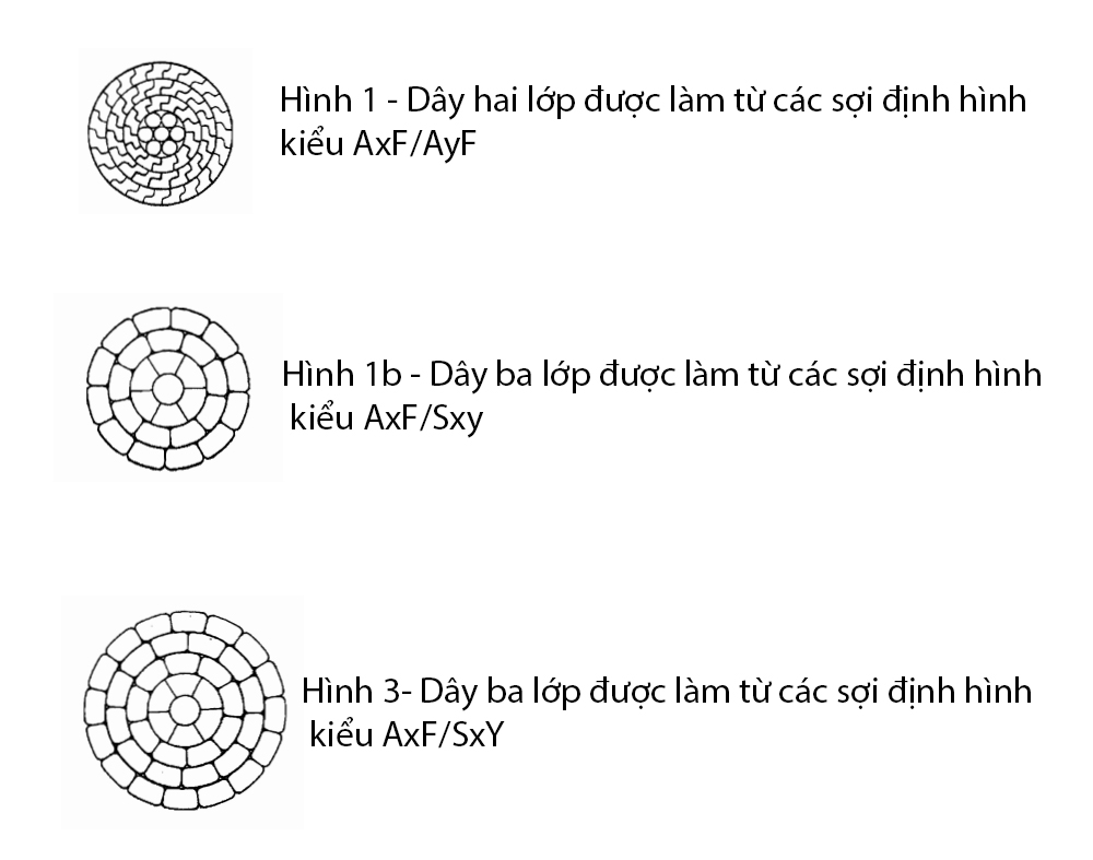
In this standard three production methods are given. The first method uses yarns that are shaped in one process and twisted in another. The second method shapes the yarns and then twists them in the same operation. In the third method, first twist a layer of circular yarns and then press the layer together to have a circular cross-section. Additional layers of yarn can be twisted and pressed or additional layers of profiled yarn can be twisted on the laminated core.
In these methods, the material shall comply with IEC 60889 or IEC 60104.
In the first method, the test shall be made on the profiled yarns before twisting and the characteristics shall be based on the equivalent yarn diameter. In the remaining methods, the test shall be made on round yarns before forming and twisting and the properties shall be based on the round yarn diameter before forming.
If testing on separate yarns after twisting is required, the purchaser and manufacturer shall agree on the requirements prior to ordering.
Typical profiled wire types are shown in Figures 1a, 1b and 2.
5.3. Wire size
A list of wire sizes is given in Annex D as a guide. When new design, wire sizes should be selected according to that category. Wires with diameters and mechanical properties equal to existing or established wire designs are also given in Annex D to assist in the selection of wire to be used in place of bare wires on power transmission lines. current overhead.
Other wire sizes and twists not covered by this standard may be designed and supplied by agreement between manufacturer and purchaser, and the relevant requirements of this standard shall then apply. this standard.
5.4. Surface
The wire surface shall be free from defects visible to the naked eye (correcting lenses are allowed) such as scratches, dents, etc., which are not suitable for commercial practice.
5.5. Twisting way
5.5.1. All strands of the rope must be concentrically twisted. The adjacent layers of yarn must be twisted in opposite directions. The outermost layer must be twisted “right” unless otherwise specified in the purchase order.
5.5.2. The yarns of each layer must be twisted evenly and tightly around the yarn(s) of the underlying layer.
5.5.3. The pitch ratio for layers of steel wire shall be as follows:
a) the pitch ratio for a 6-strand layer of a 7-strand or 19-strand steel core shall be not less than 16 and not more than 26;
b) the pitch ratio for the 12-strand layer of a 19-strand steel core shall be not less than 14 and not more than 22;
c) for certain wire structures, as illustrated in Figure 1b, the minimum pitch ratio may be less than 10 for both the inner and outer layers.
5.5.4. The pitch ratio for the aluminum layer of all wires shall be as follows:
a) the pitch ratio for the outer layer of aluminum thread shall be not less than 10 and not more than 14;
b) the pitch ratio for the inner layer of aluminum thread shall be not less than 10 and not more than 16;
5.5.5. In a 19-strand steel core, the pitch ratio of the 12-strand layer shall not be greater than that of the 6-strand layer. Likewise, in a multilayer aluminum wire, the pitch ratio of any aluminum layer should not be greater than that of the underlying aluminum layer.
5.5.6. All steel threads must be in place naturally in the helix core, and when the core is cut, the ends should remain in place, or can be easily repositioned by hand and then that stays in place. This requirement also applies to the outer layers of aluminum fibers.
5.5.7. Before twisting, all aluminum and steel filaments must have approximately the same temperature.
5.6. Joint
5.6.1. On the cored wire and on any ropes, there shall not be any joints in any way, during the twisting process.
5.6.2. On each length of wire, no aluminum wire shall be used with more than one joint as permitted by reference to IEC 61089.
5.6.3. During the torsion process, it is not allowed to weld a single aluminum wire in order to achieve the specified wire length.
5.6.4. During twisting, it is permissible to join inevitable breaks in aluminum threads, provided that such breaks are not caused by inherently defective aluminum filaments or by the use of short aluminum filaments. The splices shall conform to the shape of the original yarn, i.e. the joints shall be honed to a shape equal to the shape of the yarns containing the splice and free from twisting.
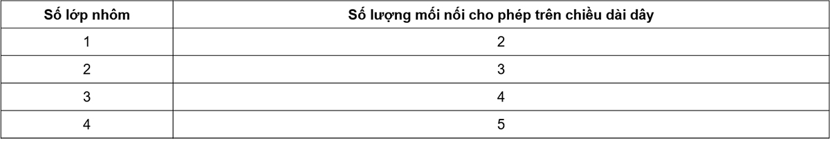
5.6.5. For aluminum strand, the number of splices shall not exceed the values specified in Table 1. The splices shall be at least 15 m apart on the same strand, or on any other aluminum strand of the finished wire.
5.6.6. Joints shall be made by contact welding, contact welding and then cold forging or cold pressing (see note 1) and other approved methods. Welds shall be made in accordance with commercial practice. The first weld of the joint shall be electrically re-annealed over a length of approximately 250 mm on each side of the weld.
While it is not required that the joints specified in 5.6.4 meet the requirements of the original yarn (see note 2), they shall withstand stresses not less than 75 MPa for the annealed solder joints; and not less than 130 MPa for cold pressed welded joints or electric contact and cold forged joints. The manufacturer shall demonstrate that the welding method is capable of meeting the specified requirements for strength.
NOTE 1 It is customary in some countries to require re-annealing of cold pressed joints for materials A2 or A3.
Note 2 to entry: The performance of joints on wires of a wire, if properly arranged, is related to both tensile strength and elongation. Because of its better elongation properties, an annealed electric weld has less strength, but in general features resembles that of a cold weld or a cold-pressed electric weld.
5.7. Density in length – Mass per unit length
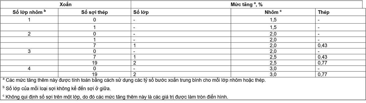
The mass given in the tables of Annex D is calculated for each wire size and twist, using the densities of aluminum and galvanized steel wires given in the standards given in 5.1, the increase due to the torsion given in Table 2 and the cross-sectional areas of the aluminum and galvanized steel wires based on their theoretical diameters unrounded.
The mass gain due to torsion (see note 1), as a percentage based on the average pitch ratios given in 5.5.4 and 5.5.5, shall be taken according to Table 2 or, if more precise is required. , the actual pitch ratios can be used to calculate the actual mass gain.
When the wire needs to be greased (see Note 2), the nominal mass of the grease shall be calculated according to the method given in Annex C.
NOTE 1 The mass of the helix is affected by the pitch ratio. Except for the middle yarn, all the remaining yarns are longer than the rope, and the extra mass depends on the ratio of twists used.
NOTE 2 Grease requirements are under consideration.
NATIONAL STANDARDS
TCVN 8090 : 2009
IEC 62219 : 2002
Ceiling WIRE FOR Aerial ELECTRICAL TRADE LINES – Ceiling WIRE HAS TOOLS IN CONFIDENTIAL CLASSES
Overhead electrical conductors – Formed wire, concentric lay, stranded conductors
Preface
TCVN 8090: 2009 replaces TCVN 5064: 1994;
TCVN 8090 : 2009 is completely equivalent to IEC 62219 : 2002
TCVN 8090: 2009 compiled by the National Standard Technical Committee TCVN/TC/E4/SC1 PVC-insulated wires and cables, proposed by the General Department of Standards, Metrology and Quality, and published by the Ministry of Science and Technology. .
Ceiling WIRE FOR Aerial ELECTRICAL TRADE LINES – Ceiling WIRE HAS TOOLS IN CONFIDENTIAL CLASSES
Overhead electrical conductors – Formed wire, concentric lay, stranded conductors
1. Scope of application
This standard specifies the electrical and mechanical properties of overhead wires concentrically twisted, with shaped or shaped yarn before, during or after twisting, and manufactured from a combination of alloys. following metals:
a) hard-drawn aluminum, designated A1 according to IEC 60889;
b) hard-drawn aluminum, designated A1F according to IEC 60889 and shaped before twisting;
c) hard-drawn aluminum alloy, designated A2 or A3 according to IEC 60104;
d) hard-drawn aluminum alloy, designated A2F or A3F according to IEC 60104 and shaped before twisting;
e) normal strength steel, denoted S1A or S1B, where A and B are grades of the zinc coating for grades 1 and 2 respectively;
f) high strength steel, designated S2A or S2B;
g) very high strength steel, denoted S3A;
h) aluminum coated steel, symbol SA.
Here are some examples of possible string symbols. Other combinations are allowed.
• A1F, A2F, A3F
• A1F/S1A, A1F/S1B, A1F/S2B, A1F/S3A
• A1F/A1, A1F/A2, A1F/A3
• A1F/SA, A2F/SA, A3F/SA
Other wire types not mentioned above are by no means excluded.
2. References
TCVN 8095-466:2009 (IEC 60050-466: 1990), International Electrotechnical Vocabulary – Part 466: Overhead transmission lines
IEC 60104:1987, Aluminum-magnesium-sillicon alloy wire for overhead line conductors
IEC 60888:1987, Zinc-coated steel wires for stranded conductors
IEC 60889:1987, Hard-drawn aluminum wire for overhead line conductors
TCVN 6483:1999 (IEC 61089:1991), Concentric layers of round stranded bare wire for overhead power transmission lines
IEC 61232:1993, Aluminum-clad striel wires for electrical purposes
IEC 61395:1998, Overhead electrical conductors – Creep test procedures for stranded conductors
3. Definition
In this standard, the following definitions apply:
3.1. Aluminum (aluminum)
All grades of aluminum and aluminum alloys are included.
3.2. Bare wire (conductor)
material used to carry electric current consisting of many strands twisted together and between them without insulation
3.3. Concentric lay stranded conductor
A wire consisting of a central core surrounded by one or more layers of closely spaced yarns, twisted in opposite directions.
3.4. Direction of lay
3.4.1. Direction of lay (general definition)
The direction of twist of a layer of yarn from the observer’s side.
NOTE Right direction is clockwise and left direction is counterclockwise. [TCVN 466-10-07, modified]
3.4.2. Direction of lay (alternative definition)
The torsion direction is defined as the right or left direction.
NOTE For the right direction, the threads are in the same direction as the center part of the Z when the wire is placed vertically. For the left side, the threads are in the same direction as the middle part of the S when the string is placed vertically.
3.5. Equivalent wire diameter
Diameter of a circular thread having the same cross-sectional area, mass and resistance as a given profile of the same material.
3.6. compactness ratio
The ratio of area 1 to area 2 where area 1 is the total cross-sectional area of the wire including the core, and area 2 is the area of a circle whose diameter is equal to the outside diameter of the wire.
3.7. Fill ratio
Area 1/(area 2 – area 3) where area 1 is the cross-sectional area of the aluminum part of the wire, area 2 is the area of a circle with a diameter equal to the outside diameter of the wire and the area area 3 is the area of a circle circumscribed to the core of the composite wire (area 3 is zero for a homogeneous wire).
3.8. Formed wire
The metal thread has a constant cross-section and has a non-circular shape.
3.9. Lay length (lay length)
The axial length of a complete helix formed by a separate strand of the helix.
3.10. lay ratio
Ratio of the pitch length to the outside diameter of the respective layer of yarns of the helix. [TCVN 466-10-06, modified]
3.11. Lot (lot)
set of wires manufactured by the same manufacturer, under identical manufacturing conditions
NOTE A lot may include part or all of the wire purchased.
3.12. Nominal (nominal)
Name or identifier of a measurable characteristic, by which a wire or a component of it can be identified, for which the tolerances to be applied can be determined.
NOTE The nominal values should be the target values.
3.13. Round wire
Pulled metal thread, of constant circular cross-section.
3.14. Steel Ratio
Ratio of the area of steel to the area of aluminum, in percent, for wires marked AxF/Syz.
4. Symbol system
The symbology used to identify twisted wires made of aluminum profiles, with or without steel threads.
The uniform aluminum wire is designated AxF, where x is the aluminum type designation.
Aluminum composite wire is designated as AxF/Ay or AxF/AyF, where AxF stands for the outer (or sheathed) strands and Ay or AyF stands for the inner (or core) fibers.
Aluminum wire – mixed steel is denoted by AxF/Syz or AxF/SA, where AxF is the symbol for the outer aluminum wires (outer envelope) and Syz or SA is the symbol for the inner steel core. In galvanized steel wire designation, y is the steel grade (normal strength, high strength or very high strength) and z is the type of zinc coating (A or B).
Wires are identified as follows:
a) a code indicating the equivalent conductive part of aluminum A1F, in mm2;
b) a code representing the core material area, in mm2, if used;
c) the symbol indicating the type of fiber that makes up the bare wire. For mixed wires, the first symbol represents the outer layer, the second symbol represents the core;
d) numerals representing the nominal wire diameter.
Example 1: 500-A1F-262: the wire is made of A1F aluminum profiles. The area is 500 mm2, the diameter is (262 x 0.1) mm.
Example 2: 505/65-A1F/S1A-281: the wire is made of A1F aluminum profiles and S1A normal strength steel thread with grade 1 zinc coating. The A1F aluminum area is 505 mm2. area of steel S1A is 65 mm2. The nominal diameter of the wire is (281 x 0.1) mm.
Below are examples of several types of wire. Other combinations are allowed.
• A1F, A2F, A3F
• A1F/S1A, A1F/S1B, A1F/S2A, A1F/S2B, A1F/S3A
• A1F/A1, A1F/A1, A1F/A3
• A1F/SA, A2F/SA, A3F/SA
5. Requirements for twisted wire
5.1. Material
Twisted wire shall be made from aluminum profiles and, upon request, additional aluminum or galvanized steel round or aluminum strand. Before twisting, all fibers shall have the characteristics specified in IEC 60104, IEC 60888, IEC 60889 or IEC 61232 where applicable (see note). Threads that are shaped before twisting shall have properties calculated based on their equivalent circular yarn diameters.
NOTE The resistivity of these metals is as follows (in ascending order):
– A1F: 28,264 nΩxm (corresponding to 61% IACS);
– A2F: 32,530 nΩxm (corresponding to 53% IACS);
– A3F: 32,840 nΩxm (corresponding to 52.5% IACS);
5.2. Shaped yarn
In this standard three production methods are given. The first method uses yarns that are shaped in one process and twisted in another. The second method shapes the yarns and then twists them in the same operation. In the third method, first twist a layer of circular yarns and then press the layer together to have a circular cross-section. Additional layers of yarn can be twisted and pressed or additional layers of profiled yarn can be twisted on the laminated core.
In these methods, the material shall comply with IEC 60889 or IEC 60104.
In the first method, the test shall be made on the profiled yarns before twisting and the characteristics shall be based on the equivalent yarn diameter. In the remaining methods, the test shall be made on round yarns before forming and twisting and the properties shall be based on the round yarn diameter before forming.
If testing on separate yarns after twisting is required, the purchaser and manufacturer shall agree on the requirements prior to ordering.
Typical profiled wire types are shown in Figures 1a, 1b and 2.

Hình 1a – Dây ba lớp được làm từ các sợi định hình kiểu AxF/SxY

Hình 1b – Dây ba lớp được làm từ các sợi định hình kiểu AxF/Sxy
Hình 1 – Dây được làm từ các sợi định hình – Ba lớp

Hình 2 – Dây hai lớp được làm từ các sợi định hình kiểu AxF/AyF
5.3. Wire size
A list of wire sizes is given in Annex D as a guide. When new design, wire sizes should be selected according to that category. Wires with diameters and mechanical properties equal to existing or established wire designs are also given in Annex D to assist in the selection of wire to be used in place of bare wires on power transmission lines. current overhead.
Other wire sizes and twists not covered by this standard may be designed and supplied by agreement between manufacturer and purchaser, and the relevant requirements of this standard shall then apply. this standard.
5.4. Surface
The wire surface shall be free from defects visible to the naked eye (correcting lenses are allowed) such as scratches, dents, etc., which are not suitable for commercial practice.
5.5. Twisting way
5.5.1. All strands of the rope must be concentrically twisted. The adjacent layers of yarn must be twisted in opposite directions. The outermost layer must be twisted “right” unless otherwise specified in the purchase order.
5.5.2. The yarns of each layer must be twisted evenly and tightly around the yarn(s) of the underlying layer.
5.5.3. The pitch ratio for layers of steel wire shall be as follows:
a) the pitch ratio for a 6-strand layer of a 7-strand or 19-strand steel core shall be not less than 16 and not more than 26;
b) the pitch ratio for the 12-strand layer of a 19-strand steel core shall be not less than 14 and not more than 22;
c) for certain wire structures, as illustrated in Figure 1b, the minimum pitch ratio may be less than 10 for both the inner and outer layers.
5.5.4. The pitch ratio for the aluminum layer of all wires shall be as follows:
a) the pitch ratio for the outer layer of aluminum thread shall be not less than 10 and not more than 14;
b) the pitch ratio for the inner layer of aluminum thread shall be not less than 10 and not more than 16;
5.5.5. In a 19-strand steel core, the pitch ratio of the 12-strand layer shall not be greater than that of the 6-strand layer. Likewise, in a multilayer aluminum wire, the pitch ratio of any aluminum layer should not be greater than that of the underlying aluminum layer.
5.5.6. All steel threads must be in place naturally in the helix core, and when the core is cut, the ends should remain in place, or can be easily repositioned by hand and then that stays in place. This requirement also applies to the outer layers of aluminum fibers.
5.5.7. Before twisting, all aluminum and steel filaments must have approximately the same temperature.
5.6. Joint
5.6.1. On the cored wire and on any ropes, there shall not be any joints in any way, during the twisting process.
5.6.2. On each length of wire, no aluminum wire shall be used with more than one joint as permitted by reference to IEC 61089.
5.6.3. During the torsion process, it is not allowed to weld a single aluminum wire in order to achieve the specified wire length.
5.6.4. During twisting, it is permissible to join inevitable breaks in aluminum threads, provided that such breaks are not caused by inherently defective aluminum filaments or by the use of short aluminum filaments. The splices shall conform to the shape of the original yarn, i.e. the joints shall be honed to a shape equal to the shape of the yarns containing the splice and free from twisting.
5.6.5. For aluminum strand, the number of splices shall not exceed the values specified in Table 1. The splices shall be at least 15 m apart on the same strand, or on any other aluminum strand of the finished wire.
5.6.6. Joints shall be made by contact welding, contact welding and then cold forging or cold pressing (see note 1) and other approved methods. Welds shall be made in accordance with commercial practice. The first weld of the joint shall be electrically re-annealed over a length of approximately 250 mm on each side of the weld.
Table 1 – Permissible number of splices on aluminum wires
| Number of aluminum layers | Allowable number of splices per wire length |
| first | 2 |
| 2 | 3 |
| 3 | 4 |
| 4 | 5 |
While it is not required that the joints specified in 5.6.4 meet the requirements of the original yarn (see note 2), they shall withstand stresses not less than 75 MPa for the annealed solder joints; and not less than 130 MPa for cold pressed welded joints or electric contact and cold forged joints. The manufacturer shall demonstrate that the welding method is capable of meeting the specified requirements for strength.
NOTE 1 It is customary in some countries to require re-annealing of cold pressed joints for materials A2 or A3.
Note 2 to entry: The performance of joints on wires of a wire, if properly arranged, is related to both tensile strength and elongation. Because of its better elongation properties, an annealed electric weld has less strength, but in general features resembles that of a cold weld or a cold-pressed electric weld.
5.7. Density in length – Mass per unit length
The mass given in the tables of Annex D is calculated for each wire size and twist, using the densities of aluminum and galvanized steel wires given in the standards given in 5.1, the increase due to the torsion given in Table 2 and the cross-sectional areas of the aluminum and galvanized steel wires based on their theoretical diameters unrounded.
The mass gain due to torsion (see note 1), as a percentage based on the average pitch ratios given in 5.5.4 and 5.5.5, shall be taken according to Table 2 or, if more precise is required. , the actual pitch ratios can be used to calculate the actual mass gain.
When the wire needs to be greased (see Note 2), the nominal mass of the grease shall be calculated according to the method given in Annex C.
NOTE 1 The mass of the helix is affected by the pitch ratio. Except for the middle yarn, all the remaining yarns are longer than the rope, and the extra mass depends on the ratio of twists used.
NOTE 2 Grease requirements are under consideration.

5.8. String strength
5.8.1. The rated tensile strength of a uniform aluminum wire is taken as the sum of the minimum tensile strengths of all strands, as determined in 5.8.4.
5.8.2. The rated tensile strength of an AxF/Syz or AxF/SA composite wire is the sum of the tensile strength of aluminum and the strength of the steel to an elongation consistent with that of aluminum at the tensile load value. For technical and practical conditions, the strength of steel is considered conservatively, taken as the tensile force corresponding to an elongation of 1 % per 250 mm of length.
5.8.3. The rated tensile strength of mixed aluminum wires (A1F/A2 or A1F/A3) is the sum of the tensile strength of A1F and 95% of the tensile strength of A2 or A3.
5.8.4. The tensile strength of any single yarn is the product of its nominal cross-section with the appropriate minimum stress given in the standards given in 5.1.
6. Tests
6.1. Classification of tests
6.1.1. Typical test
The type test is used to check the main characteristics of the wire, which are dependent on the design of the wire. These tests are carried out once on a new design, or on a new wire manufacturer or process, and are then repeated only when there is a change in design, manufacturer or procedure. fabrication process.
Type tests are carried out only on cords that have satisfied all the requirements of the relevant sample tests.
For established designs, type test data shall be provided.
6.1.2. Sample test
Sample testing is intended to ensure the quality of wires and compliance with the requirements of this standard.
6.2. Test requirements for new wire designs
The test requirements shall be as follows:
6.2.1. Typical test
a) Joints in aluminum threads
b) Stress-strain
c) Wire breaking tensile strength
d) Stretch
6.2.2. Sample test
a) On yarn before twisting: according to 5.1 and 5.2
b) On the wire:
– cross-sectional area;
– outside diameter;
– density in length;
– surface conditions;
– ratio of pitch and helix direction of the layer;
– the wrapping test is carried out on aluminum filament taken from there, where forming and twisting are carried out in the same operation.
6.3. Sample size
Samples for the tests specified in 6.2.2 are selected at random from the outer end of 10% of the windings. However, a wire surface condition check shall be carried out on all reels.
6.4. Sample length
6.4.1. Samples for testing on individual aluminum strands and, where applicable, on cored aluminum or galvanized steel wires, shall be taken prior to twisting, and tested in accordance with the standards given. in 5.1.
6.4.2. Samples for testing individual strands after twisting shall, when required, be a length of 1,5 m cut from the outer end of the coils or reels.
6.4.3. The specimen length required for tensile and stress-strain tests shall be at least 400 times the diameter of the bare wire but not less than 10 m.
6.4.4. The length of the specimen in this subclause is the minimum length specified to obtain a high degree of accuracy for the stress-strain curve. Where the manufacturer can demonstrate that the shorter test pieces provide equivalent accuracy by comparative test results and are accepted by the purchaser, shorter test pieces may be used.
6.5. Typical test
6.5.1. Joints in aluminum threads
The manufacturer shall demonstrate to the purchaser that the method used to join the aluminum threads meets the strength requirements of 5.6, either by providing the purchaser with the latest test results or by conducting perform the necessary tests.
6.5.2. Stress-strain curve
Stress-strain curves shall be supplied as a type test upon request by the purchaser and shall best represent the performance of the rope under load.
If agreed between purchaser and supplier when ordering, the stress-strain tests shall be carried out on the wire and, where applicable, on the core, according to the method given in annex B. .
6.5.3. Tensile test of wire
When a wire breaking strength test is required, not a single wire of the wire shall break before reaching 95% of their rated tensile strength according to 5.8.
The breaking strength of the wire is determined by pulling the wire on a suitable tensile testing machine with an accuracy of at least ± 1%. The rate of increase in traction should be in accordance with B.6. For the purposes of this test, suitable terminals shall be fitted at both ends of the wire sample. During the test, the breaking tensile strength of the rope is determined by the tensile force achieved at the moment of breaking of one or more strands. Retesting – or up to three tests in total – may be permitted if the yarn breaks within 1 cm of the connector and the tensile strength has not yet reached the specified breaking force.
6.5.4. Stretch test
The creep test, when required, shall be carried out in accordance with IEC 61395.
6.6. Sample test
6.6.1. Cross-sectional area
6.6.1.1. The cross-sectional area of the aluminum part of the twisted wire shall be taken as the sum of the cross-sectional areas of the resulting aluminum strands, on the basis of the diameter measurements required by 6.6.1.4 or 6.6.1.5.
6.6.1.2. This area shall not deviate from the nominal value by more than ±2% in each test piece, and not more than ±1.5% of the mean of the four measurements, at randomly selected locations with a maximum distance from each other. at least 20 cm.
6.6.1.3. The core area, if applicable, is taken to be equal to the sum of the areas of the solid fibers constituting the core, on the basis of the diameter measurement in accordance with 6.6.1.4.
6.6.1.4. The diameter of a thread shall include plating, if any, and shall be measured with a flat-surface micrometer caliper at both the stopper and shaft end and shall be readable in millimeters to two digits after the decimal point. The diameter in millimeters shall be the average of three measurements, each taking the average of the maximum and minimum readings at the measuring point near the ends and at the center of the test piece.
6.6.1.5. The equivalent yarn diameter of the profiled yarn is calculated using the load, length and density as described in IEC 60889.
6.6.2. Wire diameter
The wire diameter shall be measured midway between the torsion die and the winch of the twisting machine.
Measurements shall be made with a caliper ensuring one-hundredth of a millimeter (0,01 mm) readings. The diameter shall be the average of two readings, rounded to the nearest hundredth of a millimetre, taken at right angles to each other at the same position.
The wire diameter shall not differ by more than ± 1% for diameters greater than or equal to 10 mm and by more than ± 0.1% for diameters less than 10 mm.
6.6.3. Density in length – Mass per unit length
The length density (mass per unit length) of the wire is determined using an instrument capable of achieving an accuracy of ±0.1%.
The tolerance on mass of wire per unit length without grease shall be not more than ± 2%.
The mass of grease in a wire shall be determined by the difference between the mass of the greased wire and the mass of the wire after degreasing. The mass of grease shall not be less than the minimum value specified in Annex C.
6.6.4. Tensile strength of fibers
When required, tests for breaking tensile strength are carried out on yarns taken from twisted ropes. The yarn test piece shall be taken from the wire specimen and straightened, but care shall be taken not to stretch.
The yarn cross-sectional area is determined from the diameter measurements made in accordance with 6.6.1.3 and 6.6.1.4 in the case of profiled yarns. The straightened yarn is placed on a suitable tensile testing machine. The pulling force shall be raised slowly, with a rate of displacement of the clamps of the testing machine not less than 25 mm/min and not more than 100 mm/min.
Tensile strength at break of pre-twisted yarns shaped by the cross-sectional area of the yarn shall not be less than 95% of the stress required before twisting (5 % reduction is due to handling and winding considerations). during torsion). For yarns shaped after twisting, see 5.2.
6.6.5. Surface Condition
The surface of the wire shall conform to the requirements of 5.4.
6.6.6. Ratio of pitch and torsion of the layer
The pitch ratio of each layer of wire is determined by the ratio of the measured pitch length of the layer to the outside diameter of the same layer.
The values obtained shall conform to the requirements of 5.5. In addition, the direction of twist of each layer shall also comply with the requirements of 5.5 and shall be recorded.
6.7. Check
The manufacturer shall notify the purchaser at the time of purchase of the place and date of sample and type testing. The manufacturer shall provide the purchaser’s representative tester with all necessary and sufficient testing competence to convince the inspector that the products conform to this standard.
Where inspection is carried out by the buyer prior to shipment, all tests shall be carried out within 10 days, after the buyer has received notice that all equipment, materials are ready. For the test, the material shall be accepted or rejected immediately at the manufacturer’s workshop. If the purchaser does not have a representative present at the manufacturer’s workshop to test the material after the above 10 days have expired, the manufacturer shall carry out the tests described in this document and provide copies. official test results to the purchaser, upon request, upon the results of the above tests. The purchaser shall accept or reject the material according to the results of such tests.
Alternatively, the manufacturer may provide relevant test results to the purchaser, if such tests have been carried out during production.
6.8. Accept or reject
Failure of a test sample to meet any of the requirements of this standard shall constitute a condition for rejection of the lot represented by this sample.
If a lot is thus rejected, the manufacturer has the right to test all reels in this batch only once and submit the required reels for acceptance.
7. Packaging and labeling
7.1. Packaging
The rope should be suitably protected against damage that may occur during normal handling and transportation.
The following items shall be agreed between manufacturer and purchaser at the time of ordering or as soon as practicable:
a) type and size of packaging and method of packaging;
b) regulations on package sizes and reel holes as well as the availability of an internal terminal for grounding, where removal of the cord requires special measures.
7.2. Labeling and information on the package
Gross weight, weight excluding packaging and packing weight, length (or length and number of pieces of wire if more than one piece of rope is agreed upon on the same reel), necessary markings and identification other must be appropriately marked on the inside of the package. The same information, together with the purchase order number, manufacturer’s serial number (if applicable) and all shipping and other information must be marked on the outside of each package.
7.3. Random lines
The unavoidable random lengths of production shall not exceed 5% of the total order length, provided that none is shorter than 50% of the agreed reel length.
(rule)
INFORMATION BUYER NEED TO PROVIDE
Buyer must provide the following information:
a) number of wires;
b) cross-sectional area, symbol and twist of wire;
c) wire length per reel, tolerances and, if necessary, lengths of cord lengths;
d) type and size of packaging, method of packaging;
e) special packaging requirements, if any;
f) requirements for encapsulation materials, if any;
g) inspection, if necessary and place of inspection;
h) whether the yarns need to be tested after twisting;
i) whether welds need to be tested on threads prior to twisting;
j) whether a test for the breaking strength of the wire is required;
k) whether a stress-strain test on the wire is required;
l) torsional direction of the layer. If this information is not given, the twist direction of the outer layer is the right twist;
m) requirements for protective grease, if necessary (type, nature, etc.);
n) whether a creep test is required.
APPENDIX REMOVED
(rule)
TEST METHODS OF STRENGTH-SRETS
B.1. Sample length
Wires of the length given in 6.4.3 shall be tested to obtain a representative stress-strain curve.
B.2. Test temperature
The temperature of the sample shall be recorded, which shall not vary by more than ± 2°C during the test. Temperatures are read at the start and end of each test cycle.
B.3. Sample preparation
Samples used for testing must be carefully prepared. The relative displacement between the steel core and the aluminum fiber layers of the wire by just 1 mm also induces significant changes in the stress-strain curves. The test sample preparation shall be as follows:
Before removing the cord from the reel, use a bolted clamp to tighten the wire at a point about 5 m ± 1 m from the end of the rope. The clamping force must be large enough to prevent relative displacement between the wires of the wire.
Remove from the cord reel the desired length of wire and secure a second clamp to the cord at the required distance from the first. Wrap the tape in and then cut the wire enough distance from the clamp to accommodate the connector set.
During transport to the laboratory, the test specimen should be carefully protected against any damage. The diameter of the winding or winding shall be at least 50 times the diameter of the wire.
For stress-strain tests, terminal sets approved by the purchaser, e.g. pressurized, epoxidized, or welded connectors shall be used.
Care shall be taken not to damage any wire during the preparation of the ends of the test specimen.
Mounting of terminal sets shall not cause the fibers to sag so as not to alter the stress-strain curves of the wire.
Thread the wire into the aluminum cage. Trim the aluminum threads to make room for steel connectors, for the extension of the steel connector and the extension of the aluminum threads when clamping the aluminum sleeve. The clearance required between the aluminum threads and the steel connector before clamping is typically between 30 mm and 40 mm. Thread the steel core into the steel connector. Steel connector clamps, overlapping clamps to a maximum of 2% to 10%, starting from the outside of the cable core.
Pull the aluminum sleeve over the steel connector. Leave a space equal to 40 mm between the tip of the aluminum sleeve and the shoulder of the steel connector if the diameter of the wire is 30 mm or less, and a space equal to 50 mm if the diameter of the wire is more than 30 mm, to there is an elongation when pressed. Clamp the first stroke on the miniature mouthpiece of the aluminum telescopic tube. This secures the telescopic sleeve and prevents the aluminum from stretching towards the test piece of wire. Clamp gradually in the direction away from the test piece of wire, with small strokes of 20% the size of the metal that has not been pressed. Stop clamping before reaching the padded hollow inside the telescopic sleeve; In this part, the connector and the steel core are too small to support the clamping force on the aluminum sleeve. Continue clamping gradually toward the connector hole, on the other side of the connector filler, to clamp the telescopic sleeve over the wider part of the steel connector.
The aluminum cage shall be oriented so as not to affect the movement of the wire during the test.
B.5. Test layout
The specimen under test shall be supported over its entire length in a chute, and the chute adjusted so that the rope does not rise more than 10 mm when stretched. This should be checked by measurements and not by tensioning the wire.
The distance between the standard length thread clamp position and the aluminum telescopic mouth should be checked with a caliper during the test, to ensure that after the load cycle at 85%, when reduced to initial load, the distance This does not change by more than 1 mm from the value before the test (during the test, the length is allowed to change by more than 1 mm). 0.1 mm accuracy is enough.
Strain strain is assessed by measuring the displacement of the two ends of the reference length. The reference points are fastened to the bolt clamps to fasten the threads together. Reference plates may be used with graduated gauges or displacement sensors, but the plates must be arranged perpendicular to the wire. Twisting, lifting and shifting it from side to side by the greatest amount possible during the test shall not cause an error of more than 0.3 mm in the reading.
NOTE 1 Loose ropes can cause twisted yarns to swell outwards in the direction of a few millimeters. The bulge disappears when tension is large due to elastic deformation and reappears without tension.
Note 2 to entry: When the tensile force is large and the abnormal sounds are heard, it may be a sign of the layers of fibers slipping away, or the aluminum part slipping from the steel core due to the clamps not being tight enough. If the clamp is loosened, the slack will move towards the test piece, the landmarks are displaced with the clamp resulting in the measured strain being shorter than the actual strain.
B.6. Load test for wires
The tensile conditions for the stress-strain test of wire shall be as follows.
a) Apply an initial pull of 2 % (RTS) (rated tensile strength) to straighten the wire. Then remove the tensile force (see note 1) and adjust the strain gauge to zero at zero stress.
b) To record discontinuous stress-strain data, take strain readings at 2.5% RTS intervals rounded to the nearest kilonewton (kN).
c) Raise traction up to 30% RTS and maintain for 0.5 h. Take readings after 5 min, 10 min, 15 min and 30 min during the test cycle. Reduce the drag to the original value.
d) Raise traction up to 50% RTS and maintain for 1 h. Take readings after 5 min, 10 min, 15 min, 30 min, 45 min and 60 min. Reduce the drag to the original value.
e) Raise traction up to 70% RTS and maintain for 1 h. Take readings after 5 min, 10 min, 15 min, 30 min, 45 min and 60 min. Reduce the drag to the original value.
f) Raise traction up to 85% RTS and maintain for 1 h. Take readings after 5 min, 10 min, 15 min, 30 min, 45 min and 60 min. Reduce the drag to the original value.
g) After the fourth pull, apply the pull again and increase it steadily until the rope breaks. Take simultaneous tensile and elongation readings for up to 85% of the RTS (see note 2) at the same intervals as before.
h) The rate of increase in traction shall be uniform throughout the test. The time required to reach 30% of the RTS should be between 1 min and 2 min. Such a speed shall be maintained throughout the test.
NOTE 1 When flexible clamps are used for the test, removing the force may cause the clamp to loosen, and therefore in this case an initial pull of 2 % RTS must be maintained. maintained when adjusting strain gauges to zero.
NOTE 2 Special precautions are required when testing wires marked A1F at tensile forces above 70 % RTS.
B.7. Tensile test for steel core only
The tensile conditions for stress-strain testing of cores of AxF/Syz wires shall be as follows:
The test shall consist of several successive application of the same tensile forces as for wires at 30%, 50%, 70% and 85% of the RTS.
The core shall be subjected to a tensile force until the elongation at the beginning of each test cycle corresponds to the elongation obtained on the wire at 30, 50, 70 and 85% RTS, respectively.
B.8. Stress-strain curve
Stress-strain curves are obtained by plotting over the points 0.5 h, and 1 h at 30, 50, 70, and 85% of the RTS. For a typical curve, any aluminum slack at the lower end related to residuals in the test range due to pressured ends shall be removed. Adjust the typical curve to let it go through zero. Protection of typical stress-strain curves and curves obtained from the laboratory shall be given to the purchaser.
OLDER APPENDIX
(rule)
NORMAL VOLUME OF FIBER FOR TYPE FIBER Twisted Wires
Where it is required to grease the AxF/Syz wire to preserve the wires to reduce the risk of rust under certain environmental conditions, the mass of grease may be calculated using the method given in this annex. Since the cord is made up of profiled yarns, the gaps between the profiles are very small, only the voids in the round core need to be taken into account when calculating the fat mass.
Assuming that grease fills all voids between the fibers, the volume of grease per unit length in any layer of wire can be calculated using the following formula (see Table C.1):
 (C.1)
(C.1)
Inside
De is the outside diameter of the wire layer;
Di is the inner diameter of the wire layer;
d is the diameter or equivalent diameter of the thread in the wire layer;
n is the number of yarns in the wire layer;
Vg is the volume of fat in the wire layer.
For multilayer wires, the total mass of the grease can be calculated by adding up the values calculated for each layer.
Since there is a geometrical relationship between the parameters of Equation C.1, the total mass of grease in a wire can be expressed by the following formula:
 (C.2)
(C.2)
Inside
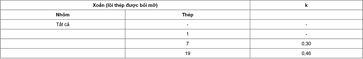
k is a factor that depends on the way the wire is twisted, the density of the grease and the fill factor (percentage of the physical volume t);
skin is the thread diameter, in millimeters;
Mg is the mass of the fat, in kg/km.
The value of k is given in Table C.1 with a grease density of 0,87 g/cm3 and a fill factor of 0.7.
EASY APPENDIX
(refer)
RECOMMENDED WIRE SIZE AND WIRE PROPERTIES
D.1. General Note
This annex gives a list of wire dimensions as a guide as well as examples of typical cross-sections of some design structures. When new design, wire sizes should be selected according to that category. Wires with diameters and mechanical properties equal to existing or established designs are also given in Annex D to assist in the selection of wires to be used in place of bare wires on overhead transmission lines. not current. Other wire sizes and twists not covered by this standard may be designed and supplied by agreement between manufacturer and purchaser, and the relevant requirements of this standard shall then apply. this standard.
The numerical code preceding the wire symbol (e.g. 500 in 500-A2F-28) represents the equivalent conductive cross-section for aluminum A1.
Wires have the same code number, have the same d.c. resistance, independent of type, symbol, and twist. The proposed wire sizes therefore allow easy selection of the best wire type when conductivity (or current-carrying capacity) is specified through a system study.
Care should be taken when replacing existing transmission lines; The carrying capacity may be the same but the heat generating area is reduced.
D.2. Calculate the properties of the wire
The wires are specified by their number followed by the material designation and then the outer diameter.
Example 1: 500-A1F-262
Example 2: 505/65-A1F/S1B-281
From these data all wire properties can be calculated, and each calculated value is rounded to significant figures in accordance with the requirements of this standard.
D.2.1. Total cross-sectional area of aluminum fibers, Aa
Aa = code x resistivity of AxF / resistivity of A1 (mm2)
This area is rounded to three significant figures for cords less than 1 000 mm2 and to four significant figures for cords greater than 1 000 mm2.
D.2.2. Diameter of the corresponding round aluminum threads, skin
leather = [(4/p)(Aa/number of aluminum threads)]0.5 (mm)
D.2.3. Diameter of the fibers in the core, ds
For layers consisting of yarns of the same diameter, the number of yarns from one layer to the next increases to 6. Therefore, when all layers of a rope have threads of the same diameter, the total number of fibers is one of the numbers: 1, 7, 19, etc…
ds = [(4/p)(Ac/number of fibers in core)]0.5 (mm)
Given a given core area (Ac), the minimum and maximum fiber sizes according to IEC 60104 and IEC 60889 will determine the number of fibers present in the core.
D.2.4. Wire Diameter, EASY
The outer diameter of the wire is the last digit of the string symbol.
D.2.5. Mass in units of length, Mc
The cross-sectional area of steel and aluminum fibers multiplied by their respective densities at 20oC is 2.70 kg/dm3 for d AxF yarn and 7.78 kg/dm3 for Syz yarn.
This result is added to the increment given in Table 2 of this standard to account for the factor due to twisted yarns.
Then, the calculated mass Mc is rounded to one digit after the decimal point.
D.2.6. Rated tensile strength, RTS
RTS is calculated according to 5.8 and rounded to one digit after the decimal point.
D.2.7. DC resistor
The d.c. resistance of the wire is calculated based on the aluminum part resistance multiplied by the increments given in Table 2. This value is expressed to four digits after the decimal point.
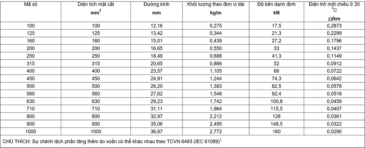
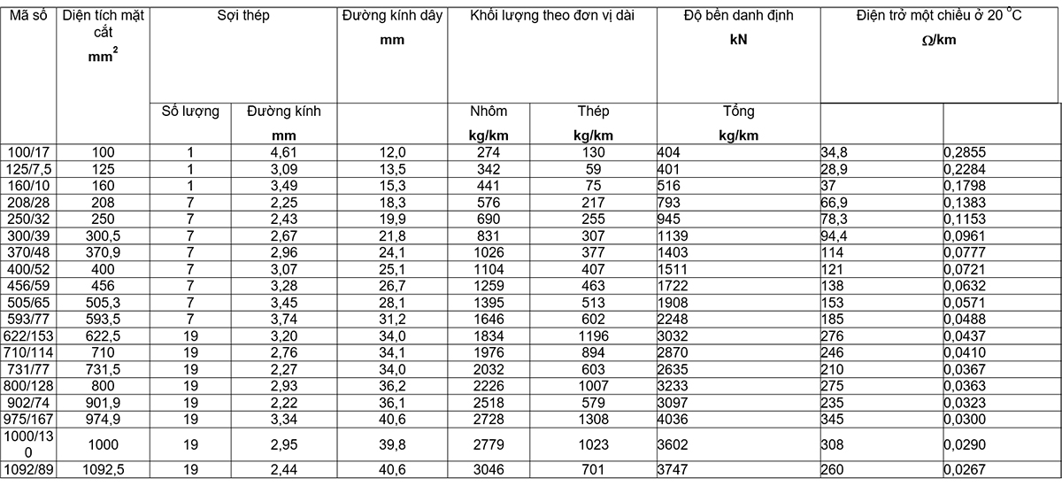
TABLE OF CONTENTS
Preface
1. Scope of application
2. References
3. Definition
4. Symbol system
5. Requirements for twisted wire
6. Tests
7. Packaging and labeling
Appendix A (regulations) – Information to be provided by the buyer
Annex B (normative) – Stress-strain test method
Annex C (normative) – Nominal mass of grease for twisted wires of profiled yarn
Annex D (reference) – Recommended wire sizes and wire properties.