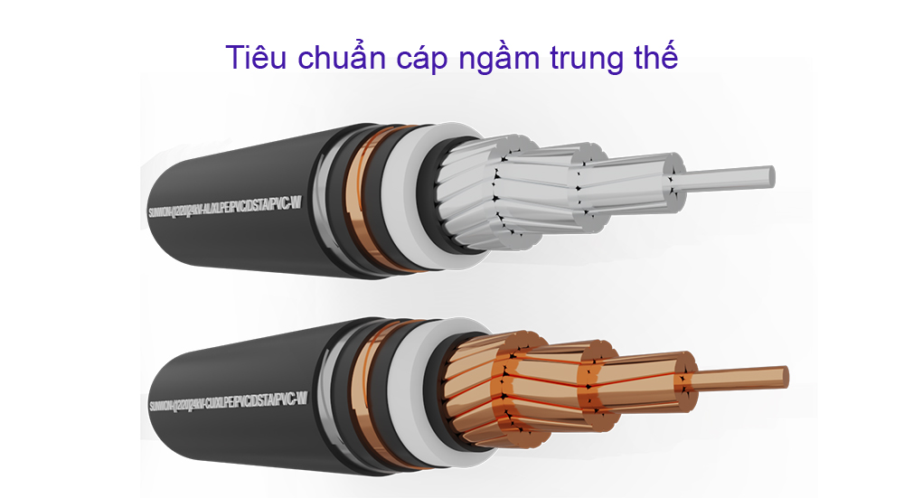
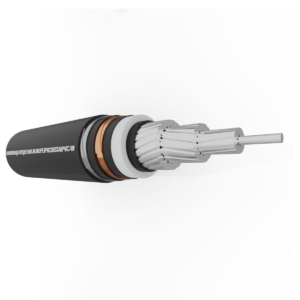
Medium voltage underground cable is an electric cable laid underground, used to transmit voltages from 1kV to 36kV and is specified in TCVN 5935-2:2013, TCVN 7997:2009. Inside:
- TCVN 5935-2:2013 regulates the structure of production of electric cables and test methods;
- TCVN 7997:2009 specifies the method of installation.
TCVN 5935-2:2013 regulates structure of medium voltage underground cables
1. Rated voltage
The rated voltage Uo/U(Um) of the cables considered in this standard is as follows: Uo/U(Um) = 3.6/6 (7.2) – 6/10 (12) – 8.7 /15 (17.5) – 12/20 (24) – 18/10 (36) kV.
2. Insulating compound
| Insulating compound | Shortened symbol |
| a) ThermoplasticsPolyvinyl chloride is used for cables with rated voltage Uo/U = 3.6/6 kV | PVC/B* |
| b) Heat hard plasticEthylene propylene rubber or the like (EPM or EPDM)
Molecular rubber or high hardness ethylene propylene rubber Cross-linked polyethylene |
EPR
HEPR XLPE |
| * Polyvinyl chloride-based insulating compounds used for cables with rated voltage Uo/U ≤ 1.8/3 kV are denoted PVC/A in IEC 60502-1. Highest conductor temperature for different types of insulating compounds | |
| Insulating compound | The highest temperature of the conductoroC | ||
| Work as usual | Short circuit(longest time is 5s) | ||
| Polyvinyl chloride (PVC/B )Conductor cross-section 300 mm2
Conductor cross-section > 300 mm2 Polyethylene (XLPE) horizontal link Rubber ethylene propylene (EPR and HEPR) |
70
70
90
90 |
160
140
250
250 |
|
3. Conductor
The conductors shall be class 1 or class 2 of uncoated or metallized annealed copper of aluminum or aluminum alloy in accordance with IEC 60228. For class 2 conductors, measures may be taken to achieve longitudinal waterproofing.
4. Insulation
a. Insulating material: The insulator shall be an extruded dielectric of one of the categories listed in the first.
b. Insulation Thickness PVC/B
| Nominal cross-sectional area of conductormm2 | Nominal thickness of insulation at rated voltage 3.6/6 (7.2) kVmm |
| 10 to 1 600 | 3.4 |
c. Insulation thickness XLPE
| Nominal cross-sectional area of conductormm2 | Nominal thickness of insulation at rated voltage Uo/U(Um) | ||||
| 3.6/6 (7.2) kVmm | 6/10 (12) kVmm | 8.7/15 (17.5) kVmm | 12/20 (24) kVmm | 18/30 (36) kVmm | |
| ten16
25 35 50 to 185 240 300 400 500 to 1600 |
2.52.5
2.5 2.5 2.5 2.6 2.8 3.0 3.2 |
–3.4
3.4 3.4 3.4 3.4 3.4 3.4 3.4 |
––
4.5 4.5 4.5 4.5 4.5 4.5 4.5 |
––
– 5.5 5.5 5.5 5.5 5.5 5.5 |
––
– – 8.0 8.0 8.0 8.0 8.0 |
NOTE 1 Conductors with a cross-sectional area less than that given in this table should not be used. However, if a smaller cross-section is required, the conductor diameter can be increased by means of a conductor screen (see 7.1) or the insulation thickness can be increased to limit the maximum electrical stresses applied to the insulation. under the test voltage at the values calculated with the smallest conductor sizes given in this table.NOTE 2 For conductors with cross-sections greater than 1 000 mm2, the insulation thickness can be increased to avoid mechanical damage during installation and service.
d. Insulation Thickness EPR/ HEPR |
|||||
| Nominal cross-sectional area of conductormm2 | Nominal thickness of insulation at rated voltage Uo/U(Um) | |||||
| 3.6/6 (7,2)kV | 6/10 (12)kV | 8.7/15 (17.5)kV | 12/20 (24)kV | 18/30 (36)kV | ||
| There is no barriermm | There is a curtainmm | mm | mm | mm | mm | |
| ten16
25 35 50 to 185 240 300 400 500 to 1 600 |
3.03.0
3.0 3.0 3.0 3.0 3.0 3.0 3.2 |
2.52.5
2.5 2.5 2.5 2.6 2.8 3.0 3.2 |
–3.4
3.4 3.4 3.4 3.4 3.4 3.4 3.4 |
––
4.5 4.5 4.5 4.5 4.5 4.5 4.5 |
––
– 5.5 5.5 5.5 5.5 5.5 5.5 |
––
– – 8.0 8.0 8.0 8.0 8.0 |
| NOTE 1 Conductors with a cross-sectional area less than that given in this table should not be used. However, if a smaller cross-section is required, the conductor diameter can be increased by means of a conductor screen (see 7.1) or the insulation thickness can be increased to limit the maximum electrical stresses applied to the insulation. under the test voltage at the values calculated with the smallest conductor sizes given in this table.NOTE 2 For conductors with cross-sections greater than 1 000 mm2, the insulation thickness can be increased to avoid mechanical damage during installation and service. | ||||||
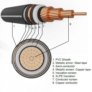
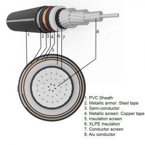
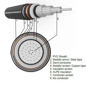
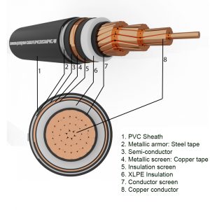
5. Curtain
a. Conductor screen
The conductor screen shall be of non-metallic material and shall be of extruded semiconductor compound, which may be placed on top of a semiconductor ribbon. The extruded semiconductor compound shall be firmly bonded to the insulation.
b. Insulation screen
The insulating screen shall consist of a non-metallic semiconductor layer combined with a metallic layer. The non-metallic layer shall be extruded directly onto the insulation of each core and made of an adherent or peelable semiconductor compound. The semiconductor ribbon or compound layer can then be placed on individual cores or core assemblies.
c. Metal curtain
The metal screen shall be one or more ribbons, or a woven mesh or a layer of concentric wire, or a combination of wires and ribbon(s).
d. Metal armor
The types of armor covered by this standard are as follows:
- Flat or round wire armor: Round or flat wire shall be galvanized steel, tinned copper or copper, aluminum or aluminum alloy. Round rope size: 0.8 – 1.25 – 1.6 – 2.0 – 3.15 mm; flat wire size: 0.8mm;
- Double Band Armor: The band must be steel, galvanized steel, aluminum or aluminum alloy. Steel strip shall be hot-rolled or cold-rolled of commercial quality. Steel strip thickness: 0.2 – 0.5 – 0.8 mm; aluminum/aluminum alloy strip thickness: 0.5 – 0.8 mm.

View products


Medium Voltage Cables
1-core underground aluminum cable SUNWON-1.8/3 (3.6) kV-AXSV 1x

Medium Voltage Cables
1-core underground copper cable SUNWON- 1.8/3 (3.6) kV-CXSV 1x


Medium Voltage Cables
1-core underground aluminum cable SUNWON- 3.6/6 (7.2) kV-AXSV 1x


Medium Voltage Cables
1-core underground copper cable SUNWON- 3.6/6 (7.2) kV- CXSV 1x


Medium Voltage Cables
1-Core Underground Aluminum Cable SUNWON- 6/10 (12) kV-AXSV 1x
Medium Voltage Cables
1-core underground copper cable SUNWON- 6/10 (12) kV- CXSV 1x
Medium Voltage Cables
1-core underground aluminum cable SUNWON- 8.7/15 (17.5) kV-AXSV 1x


Medium Voltage Cables
1-core underground copper cable SUNWON- 8.7/15 (17.5) kV- CXSV 1x

Medium Voltage Cables
1-Core Underground Aluminum Cable SUNWON- 12/20 (24) kV-AXSV 1x

Medium Voltage Cables
1-core underground copper cable SUNWON- 12/20 (24) kV- CXSV 1x


Medium Voltage Cables
1-core underground aluminum cable SUNWON-18/30 (36) kV-AXSV 1x


Medium Voltage Cables
1-core underground copper cable SUNWON-18/30 (36) kV- CXSV 1x